Verification Examples
This chapter presents analysis of many foundation examples. These examples are presented in order to
- verify the mathematical models used in ELPLA by comparing ELPLA results with closed form or another published results
- illustrate how to use ELPLA for analyzing foundation by different subsoil models
The examples discussed in this chapter cover many practical problems. For each example discussed in this book, data files and some computed files are included in ELPLA software package. The file names, contents and short description of examples are listed below. Besides, a key figure of each problem that contains the main data concerning the foundation shape, loads and subsoil is also shown.
Example 1: Stress on soil under a rectangular loaded area
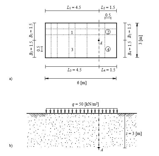
To verify the vertical stress at any point A below a rectangular loaded area, the stress on soil obtained by Das (1983) (Example 6.3, page 370) using influence coefficients of Newmark (1935) are compared with that obtained by ELPLA.
A distributed load of q = 50 [kN/m2] acts on a flexible rectangular area 6 [m] × 3 [m] as shown in Figure 1. It is required to determine the vertical stress at a point A, which is located at a depth of z = 3 [m] below the ground surface.
| Example 1: Stress on soil under a rectangular loaded area |
| ELPLA DATA-Stress on soil under a rectangular loaded area.rar |
Example 2: Stress on soil under a circular loaded area
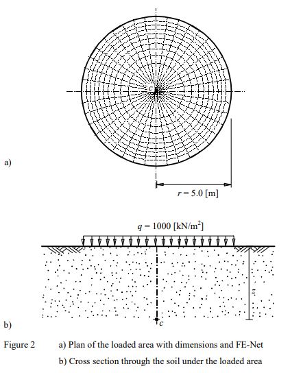
To verify the vertical stress at point c below the center of a circular loaded area, the influence coefficients of stress Iz below the center of a uniformly loaded area at the surface obtained by Scott (1974) (Table 12.2, page 287) are compared with those obtained by ELPLA.
Figure 2 shows a distributed load of q = 1000 [kN/m2] acts on a flexible circular area of radius r = 5 [m]. It is required to determine the vertical stress under the center c of the area at different depths z up to 10 [m] below the ground surface.
| Example 2: Stress on soil under a circular loaded area |
| ELPLA DATA-Stress on soil under a circular loaded area.rar |
Example 3: Immediate settlement under a loaded area on Isotropic elastic-half space medium
To verify the mathematical model of ELPLA for computing the immediate (elastic) settlement under a loaded area on Isotropic elastic-half space medium, the results of immediate settlement calculations obtained by Bowles (1977) (Table 5-4, page 157) are compared with those obtained by ELPLA.
The vertical displacement s under an area carrying a uniform pressure p on the surface of Isotropic elastic-half space medium can be expressed as............
| Example 3: Immediate settlement under a loaded area on Isotropic elastic-half space medium |
| ELPLA DATA-Immediate settlement under a loaded area on Isotropic elastic-half space medium.rar |
Example 4: Immediate settlement under a rectangular loaded area on layered subsoil
To verify the mathematical model of ELPLA for computing the immediate (elastic) settlement under a rectangular loaded area on layered subsoil, the immediate settlement of saturated clay layers under a rectangular loaded area calculated by Graig (1978) (Example 6.4, page 175) is compared with that obtained by ELPLA.
Janbu/ Bjerrum/ Kjaernsli (1956) presented a solution for the average settlement under an area carrying a uniform pressure q [kN/m2] on the surface of a limited soil layer using dimensionless factors. Factors are determined for Poisson’s ratio equal to νs = 0.5 [-].
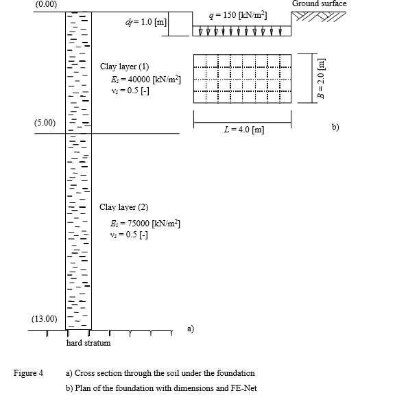
| Example 4: Immediate settlement under a rectangular loaded area on layered subsoil |
| ELPLA DATA-Immediate settlement under a rectangular loaded area on layered subsoil.rar |
Example 5: Immediate settlement under a circular tank on layered subsoil
To verify the immediate settlement under a circular loaded area calculated by ELPLA, the immediate settlement at the center of a tank calculated by Das (1983) (Example 6.2, page 354) is compared with that obtained by ELPLA.
A circular tank of 3.0 [m] diameter is considered as shown in Figure 5. The base of the tank is assumed to be flexible and having a uniform contact pressure of q = 100 [kN/m2]. A sand layer 9.0 [m] thick is located under the tank. The modulus of elasticity of the sand is Es = 21000 [kN/m2] while Poisson’s ratio of the sand is ν = 0.3 [-].
It is required to determine the immediate settlement at the center of the tank for two cases:
a) Considering the underlying soil as one layer of 9.0 [m] thickness.
b) Dividing the underlying soil into three layers of equal thickness of 3.0 [m]
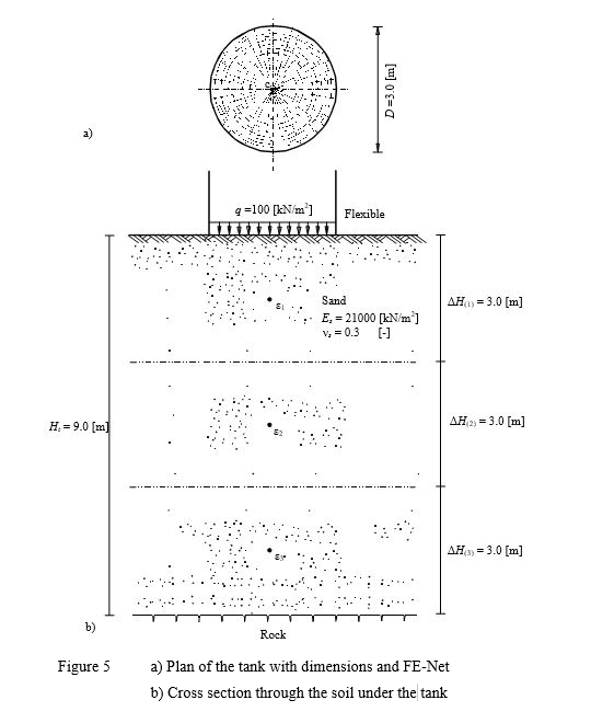
| Example 5: Immediate settlement under a circular tank on layered subsoil |
| ELPLA DATA-Immediate settlement under a circular tank on layered subsoil.rar |
Example 6: Consolidation settlement under a rectangular raft
To verify the consolidation settlement calculated by ELPLA, the final consolidation settlement of a clay layer under a rectangular raft calculated by Graig (1978) (Example 7.2, page 186) is compared with that obtained by ELPLA.
A building is supported on a raft 45 [m] × 30 [m] is considered. The contact pressure is assumed to be uniformly distributed and equal to q = 125 [kN/m2]. The soil profile is as shown in Figure 6. The coefficient of volume change for the clay is mv = 0.35 [m/MN].
It is required to determine the final settlement under the center of the raft due to consolidation of the clay.
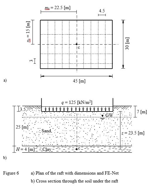
| Example 6: Consolidation settlement under a rectangular raft |
| ELPLA DATA-Consolidation settlement under a rectangular raft.rar |
Example 7: Consolidation settlement under a circular footing
To verify the consolidation settlement calculated by ELPLA, the final consolidation settlement of a clay layer under a circular footing calculated by Das (1983) (Example 6.3, page 371) is compared with that obtained by ELPLA.
A circular footing 2 [m] in diameter at a depth of 1.0 [m] below the ground surface is considered as shown in Figure 7. Water table located at 1.5 [m] below the ground surface. The contact pressure under the footing is assumed to be uniformly distributed and equal to q = 150 [kN/m2]. A normally consolidated clay layer 5 [m] thick is located at a depth of 2.0 [m] below the ground surface. The soil profile is shown in the Figure. It is required to determine the final settlement under the center of the footing due to consolidation of the clay.
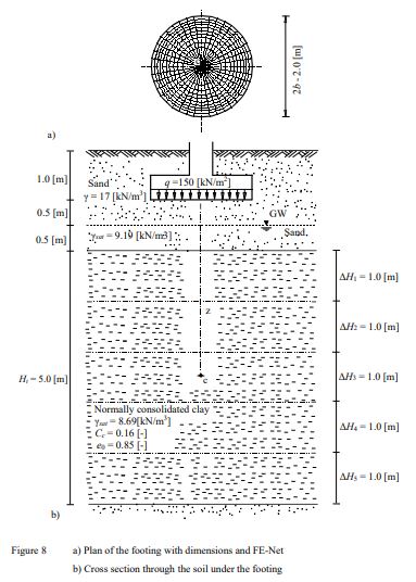
| Example 7: Consolidation settlement under a circular footing |
| ELPLA DATA-Consolidation settlement under a circular footing.rar |
Example 8: Rigid square raft on Isotropic elastic-half space medium
To verify the mathematical model of ELPLA for rigid square raft, the results of a rigid square raft obtained by other analytical solutions from Kany (1974), Fraser/ Wardle (1976), Chow (1987), Li / Dempesy (1988), and Stark (1990) (Section 5.4, page 114) are compared with those obtained by ELPLA.
The vertical displacement w [m] of a rigid square raft on Isotropic elastic-half space medium may be evaluated by ..........
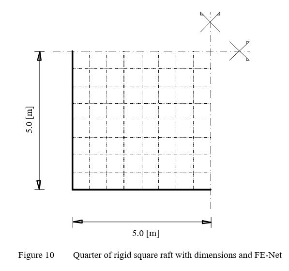
| Example 8: Rigid square raft on Isotropic elastic-half space medium |
| ELPLA DATA-Rigid square raft on Isotropic elastic- half-space medium.rar |
Example 9: Rigid circular raft on Isotropic elastic-half space medium
To verify the mathematical model of ELPLA for rigid circular raft, results of a rigid circular raft obtained by other analytical solutions from Borowicka (1939) and Stark (1990) (Section 5.2, page 106) are compared with those obtained by ELPLA.
The vertical displacement w [m] of a rigid circular raft on Isotropic elastic-half space medium may be evaluated According to Borowicka (1939).
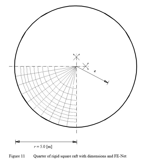
| Example 9: Rigid circular raft on Isotropic elastic-half space medium |
| ELPLA DATA-Rigid circular raft on Isotropic elastic-half space medium.rar |
Example 10: Flexible foundation and rigid raft on layered subsoil
The definition of the characteristic point so according to Graßhoff (1955) can be used to verify the mathematical model of ELPLA for flexible foundation and rigid raft. The characteristic point of a uniformly loaded area on the surface is defined as that point of a flexible settlement so is identical with the rigid displacement wo. For a rectangular area, the characteristic point takes the coordinates ac =0.87A and bc = 0.87B, where A and B are the area sides.
Figure 12 shows a raft of dimensions 8 [m] × 12 [m] resting on three different soil layers of thicknesses 7 [m], 5 [m] and 6 [m], respectively.
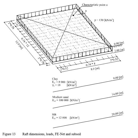
| Example 10: Flexible foundation and rigid raft on layered subsoil |
| ELPLA DATA-Flexible foundation and rigid raft on layered subsoil.rar |
Example 11: Ultimate bearing capacity for a footing on layered subsoil
To verify the ultimate bearing capacity calculated by ELPLA, the results of an example in DIN 4017 (Example 2, page 9) for determining the ultimate bearing capacity of a footing on layered subsoil are compared with those obtained by ELPLA.
A rectangular footing of 4.0 [m] × 5.0 [m] on layered subsoil is considered. Footing dimensions and soil layers under the footing with soil constants are shown in Figure 14. It is required to determine the ultimate bearing capacity of the soil under the footing.
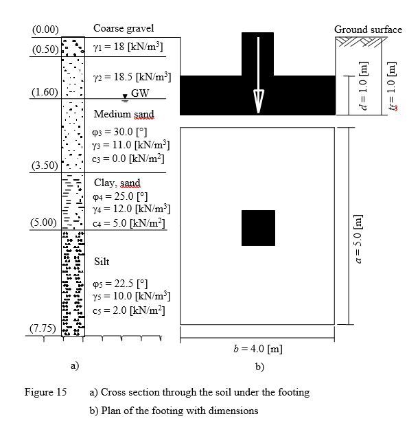
| Example 11: Ultimate bearing capacity for a footing on layered subsoil |
| ELPLA DATA-Ultimate bearing capacity for a footing on layered subsoil.rar |
Example 12: Simple assumption model for irregular raft
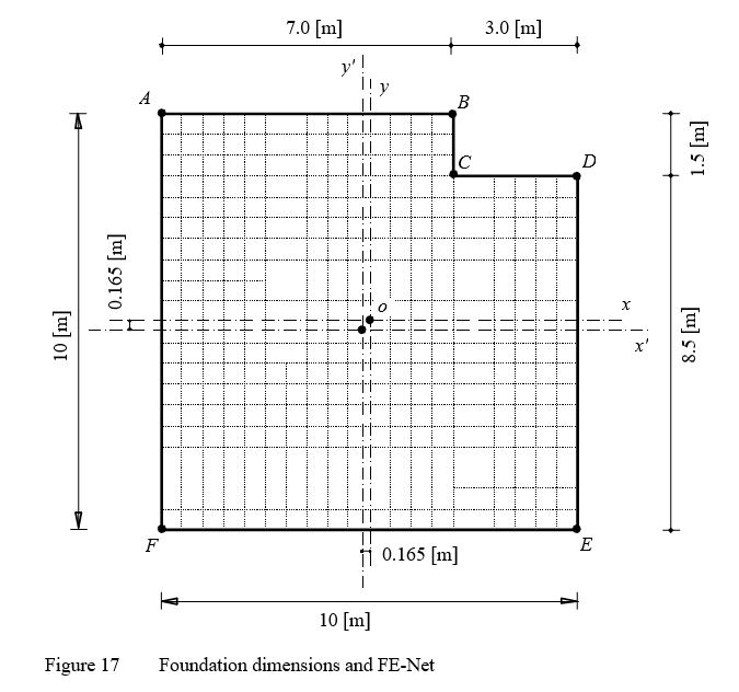
To verify the simple assumption model of ELPLA, the contact pressure distribution of an irregular foundation obtained by Bowles (1977) (Example 9-6, page 265) is compared with that obtained by ELPLA.
A square foundation has 10 [m] side is chosen. The foundation is subjected to a column load of 540 [kN] at the center. It is required to determine the distribution of the contact pressure when the corner is notched as shown in Figure 16.
The notch has the following properties:
Area A = 4.5 [m2]
Center of gravity from o in x-direction x! = 3.5 [m]
Center of gravity from o in y-direction y! = 4.25 [m]
| Example 12: Simple assumption model for irregular raft |
| ELPLA DATA-Simple assumption model for irregular raft.rar |
Example 13: Main modulus of subgrade reaction ksm
It is known that the modulus of subgrade reaction ks is not a soil constant but is a function of the contact pressure and settlement. It depends on foundation loads, foundation size and stratification of the subsoil. The main modulus of subgrade reaction ksm for a rectangular foundation on layered subsoil can be obtained from dividing the average contact pressure qo over the settlement so under the characteristic point on the foundation, which had been defined by Graßhoff (1955). Clearly, this procedure is valid only for rectangular foundations on a layered subsoil model. Determining the main modulus of subgrade reaction ksm for irregular foundation on an irregular subsoil model using another analysis is also possible by ELPLA.
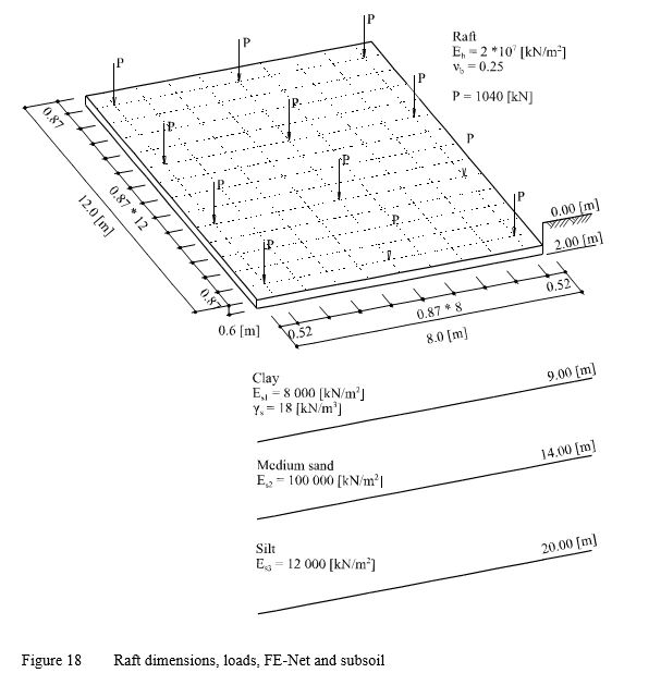
In this example, settlement calculations at the characteristic point on the raft, using Steinbrener's formula (1934) for determining the settlement under the corner of a rectangular loaded area with the principle of superposition, are used to verify ELPLA analysis for determining the main modulus of subgrade reaction ksm. Consider the square raft in Figure 17, which has area of Af = 8×12 [m] and thickness of d = 0.6 [m].
| Example 13: Main modulus of subgrade reaction ksm |
| ELPLA DATA-Main modulus of subgrade reaction Ksm.rar |
Example 14: Beam foundation on elastic springs
To verify the mathematical model of ELPLA for analyzing beam foundations, the results of beam foundation on elastic springs obtained by Rombach (2000) (Section 2.4.2, page 34) are compared with those obtained by ELPLA.
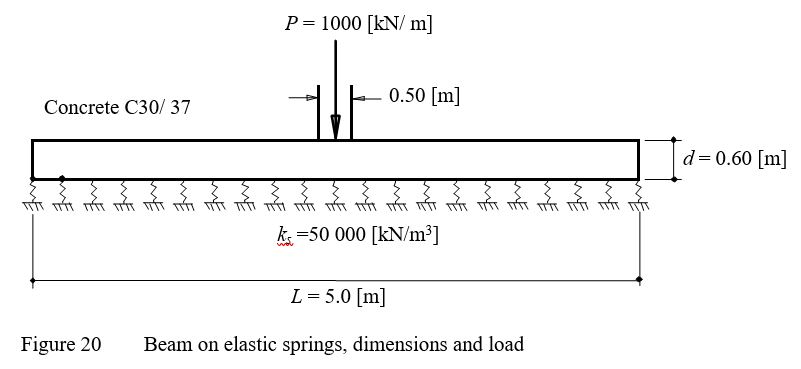
The geometry and the load of the foundation are the same as those of Rombach (2000) as shown in Figure 19. A strip foundation of thickness d = 0.60 [m] and length L = 5.0 [m] is considered.
The analysis is carried out for 1.0 [m] width stripe. The beam cross section yields Moment of Inertia I = 0.018 [m4] and Torsion modulus J = 0.045077 [m4]. The beam is subjected to a wall load of P = 1000 [kN/m] at the center.
The parameters of beam material (Concrete C30/70) are Young's modulus Eb = 3.2×10⁷[kN/m2] and Shear modulus G = 1.3×10⁷ [kN/m2]. Modulus of subgrade reaction of the soil is ks = 50000 [kN/m].
| Example 14: Beam foundation on elastic springs |
| ELPLA DATA-Beam foundation on elastic springs.rar |
Example 15: Grid foundation on elastic springs
To verify the mathematical model of ELPLA for analyzing grid foundations, the results of grid foundation on elastic springs obtained by Szilard (1986) (Example 4.4.5, page 350) are compared with those obtained by ELPLA.
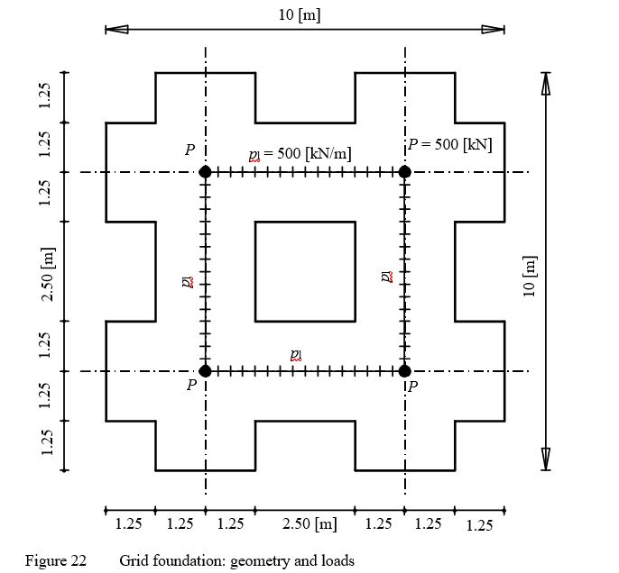
The geometry and the loads of foundation are the same as those of Szilard (1986) as shown in Figure 21. The grid has rectangular cross section of 2.5 [m] width and 0.5 [m] depth, yields Moment of Inertia I = 0.026 [m4] and Torsion modulus J = 0.091 [m4]. The parameters of grid material are Young's modulus Eb = 3×10 [kN/m] and Shear modulus Gb = 1×10 [kN/m]. Modulus of subgrade reaction of the soil is ks = 40000 [kN/m].
| Example 15: Grid foundation on elastic springs |
| ELPLA DATA-Grid foundation on elastic springs.rar |
Example 16: Elastic square raft on Isotropic elastic half-space soil medium
To verify the mathematical model of ELPLA for elastic raft, the results of an elastic raft at different relative stiffness obtained by other analytical solutions from Stark/ Majer (1988) and Borowicka (1939) are compared with those obtained by ELPLA.
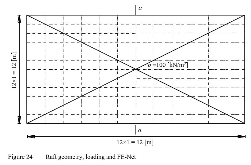
A rectangular raft with sides 12 [m] and 6 [m], rests on an isotropic elastic half-space soil medium is chosen and subdivided into 12×12 elements as shown in Figure 23. The elastic properties of the raft and the soil are Es = 10000 [kN/m], Eb = 2.6×10 [kN/m], νs = 0 [-], νb = 0.15 [-]. The raft carries a uniform load of 100 [kN/m2].
| Example 16: Elastic square raft on Isotropic elastic half-space soil medium |
| ELPLA DATA-Elastic square raft on Isotropic elastic half-space soil medium.rar |
Example 17: Winkler's model and Isotropic elastic half-space soil medium
A simple example was carried out to verify Winkler's model and Isotropic elastic half space soil medium, by comparing ELPLA results with those of Mikhaiel (1978) (Example 34, page 189) and Henedy (1987) ( Section 3.6, page 66) (or Bazaraa (1997)).
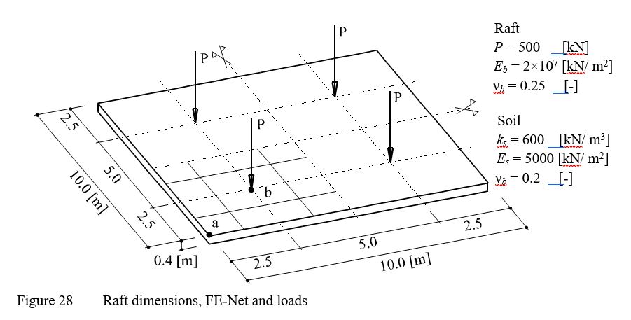
A square raft of 0.4 [m] thickness and 10 [m] side was chosen and subdivided into 64 square elements, each has dimensions of 1.25 [m] × 1.25 [m]. The raft carries four column loads, each 500 [kN] as shown in Figure 27.
| Example 17: Winkler's model and Isotropic elastic half-space soil medium |
| ELPLA DATA-Winkler's model and Isotropic elastic half-space soil medium.rar |
Example 18: Simply supported slab
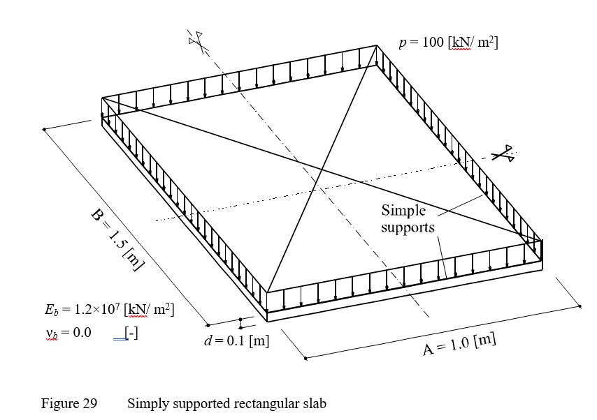
To examine the accuracy of the calculation of Finite elements-method and the convergence characteristics of the stiffness matrix, the maximum values of deflection w, moments mx, my and mxy of a simply supported rectangular slab are obtained at different nets of finite elements. The slab carries a uniform distributed load of p = 100 [kN/m2] as shown in Figure 28. The Young's modulus of the slab material is Eb = 1.2×10 [kN/m] and Poisson's ratio is νb = 0 [-]. The slab thickness is d = 0.1 [m].
| Example 18: Simply supported slab |
| ELPLA DATA-Simply supported slab.rar |
Example 19: Iteration methods
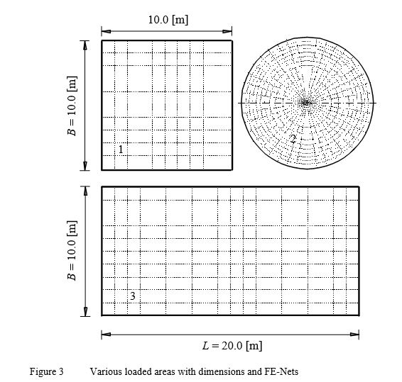
One of the difficulties to apply the Continuum model to practical problems is that the long computation time. Therefore, a comparison for time and accuracy required for analysis the raft by the Continuum model is carried out by the following calculation methods:
- Modification of modulus of subgrade reaction by iteration after Ahrens/ Winselmann (1984)
(Winkle's model/ Continuum model)
- Modulus of compressibility method for elastic raft on layered soil medium after El Gendy (1998) (Solving system of linear equations by iteration)
(Layered soil medium - Continuum model)
- Modulus of compressibility method for elastic raft on layered soil medium
(Solving system of linear equations by elimination)
(Layered soil medium - Continuum model)
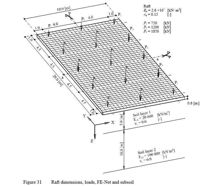
To evaluate the iterative procedures used in ELPLA, consider the raft shown in Figure 30. The raft has a dimension of 10 [m] × 20 [m] and 0.6 [m] thickness.
| Example 19: Iteration methods |
| ELPLA DATA-Iteration methods.rar |
Example 20: Influence of overburden pressure
One of the advantages of ELPLA is that the bilinear relation of deformation for the modulus of compressibility can be taken into consideration. Therefore, an example was carried out by the Modulus of compressibility method (7) to show the influence of overburden pressure on the settlements, contact pressures and moments.
A square raft has the dimension of 18×18 [m2] under an elevated water tank was chosen as shown in the Figure.
For comparison, ELPLA was used to study the influence of overburden pressure (qv, Wv) on the values of settlements, contact pressures and moments for the following three different assumptions:
a) Without taken into consideration the influence of overburden pressure, where the modulus of compressibility for reloading Ws of the soil is taken to be equal to that of loading Es.
b) The modulus of compressibility for reloading Ws of the soil is very great (Ws = 9×10⁸ [kN/m2]), where the settlement due to the reloading of the soil is nearly zero.
c) The modulus of compressibility for reloading Ws = 12447 [kN/m] is three times as the modulus of compressibility for loading Es = 4149 [kN/m], where the bilinear relation of deformation for the modulus of compressibility is taken into consideration.
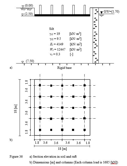
| Example 20: Influence of overburden pressure |
| ELPLA DATA-Influence of overburden pressure.rar |
Example 21: Influence of load geometry
A simple example was carried out to show the influence of load geometry on the values of settlements and internal forces for the different subsoil models. To carry out the comparison between the different soil models, three different soil models are used to analyze the raft. The three mathematical models Simple assumption, Winkler’s and Continuum models are represented by five calculation methods.
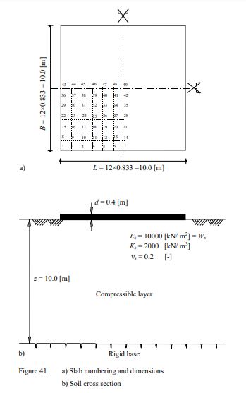
| Example 21: Influence of load geometry |
| ELPLA DATA-Influence of load geometry.rar |
Example 22: Settlement calculation under flexible foundation of an ore heap
In many cases, it is required to determine the settlement under an embankment, a metal plate foundation of a liquid tank, loads on small isolated plates or a raft of thin thickness. In these cases, the foundation will be assumed as flexible foundation.
The Figure shows an ore heap on thin concrete pavement slabs. The pavement slabs are connected with each other by movable joints. Consequently, the pavement slabs are considered as a completely flexible foundation. The unit weight of the ore material is γ = 30 [kN/m3].The foundation base under the ore heap has the dimension of 13×13 [m2], while the top area of the ore heap has the dimensions of 9×9 [m2]. The height of the ore heap is 4.0 [m] (Figure a). It is required to determine the expected settlement due to the ore heap.
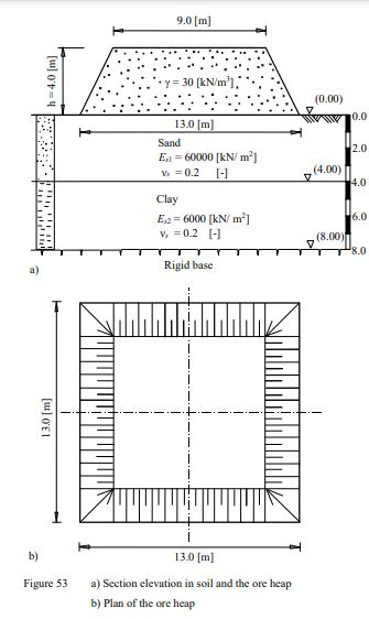
| Example 22: Settlement calculation under flexible foundation of an ore heap |
| ELPLA DATA-Settlement calculation under flexible foundation of an ore heap.rar |
Example 23: Settlement calculation for a rigid raft subjected to an eccentric load
In many cases, it is required to determine the settlement under an abutment, a bridge pier, a building core or a raft of thick thickness. In these cases, the foundation will be assumed as rigid foundation.
As an example for rigid rafts, consider the rectangular raft of a core from concrete walls shown in Figure 55 as a part of 93.0 [m] structure. The length of the raft is L = 28.0 [m], while the width is B = 25.0 [m]. Due to the lateral applied wind pressure, the raft subjected to an eccentric vertical load of P = 142000 [kN]. Figure 55 shows section elevation through the raft and subsoil, while Figure 56 shows a plan of the raft, load, dimensions and mesh.
It is required to estimate the expected settlement if the raft is considered as perfectly rigid.
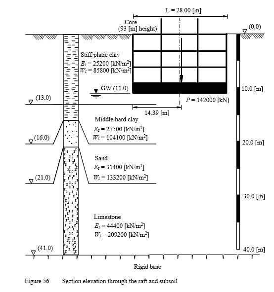
| Example 23: Settlement calculation for a rigid raft subjected to an eccentric load |
| ELPLA DATA-Settlement calculation under a rigid raft subjected to an eccentric load.rar |
Example 24: Deflection of a thin cantilever beam
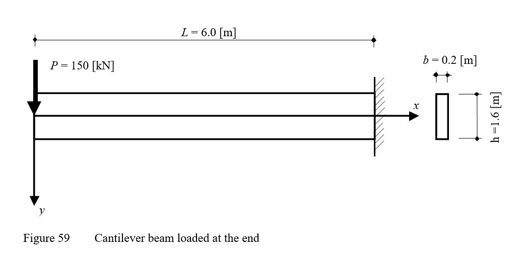
To verify the mathematical model of ELPLA for computing plane stresses, results of a cantilever beam having a thin rectangular cross section introduced by Timoshenko/ Goodier (1970) (Example 21, page 41) are compared with those obtained by ELPLA. The cantilever carries a point load of P = 150 [kN] applied at the end as shown in Figure 58.
| Example 24: Deflection of a thin cantilever beam |
| ELPLA DATA-Deflection of a thin cantilever beam.rar |
Example 25: Forces in piles of a pile group
To verify the mathematical model of ELPLA for determining pile forces of pile groups under a pile cap, results of a pile group obtained by Bakhoum (1992) (Example 5.19, page 592) are compared with those obtained by ELPLA.
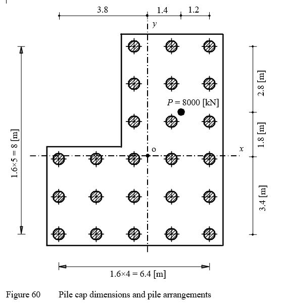
A pile cap on 24 vertical piles is considered as shown in Figure 59. It is required to determine the force in each pile of the group due to a vertical load of N = 8000 [kN] acting on the pile cap with eccentricities ex = 1.4 [m] and ey = 1.8 [m] in both x- and y-directions.
| Example 25: Forces in piles of a pile group |
| ELPLA DATA-Forces in piles.rar |
Example 26: Analysis of a continuous beam
To verify the mathematical model of ELPLA for analyzing continuous beams, results of a continuous beam introduced by Harry (1993) (Examples 10.2, 10.4 and 10.5, pages 399, 409 and 411) are compared with those obtained by ELPLA.
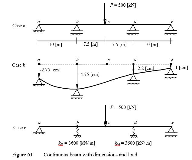
A continuous beam of length L = 35 [m] is chosen as shown in Figure 60. The beam is subjected to a point load of P = 500 [kN] at the center. The beam cross section yields Moment of Inertia I = 0.003 [m4]. Young's modulus of the beam is E = 2.0×10⁸[kN/m2].
For the comparison, three different cases are considered as follows:
Case a: Continuous beam with a point load P at the center on supports at points a, b, d and e.
Case b: Instead of the point load P at the center of the beam, points a, b, d and e have the following support settlements: Δa = -2.75 [cm], Δb = -4.75 [cm], Δd = -2.2 [cm] and Δe = -1.0 [cm].
Case c: Points c and d are supported by elastic springs that have stiffness of ksb = ksd = 3600 [kN/m].
| Example 26: Analysis of a continuous beam |
| ELPLA DATA-Continuous beam.rar |
Example 27: Moment in an unsymmetrical closed frame
To verify the mathematical model of ELPLA for analyzing unsymmetrical closed frames, moments in an unsymmetrical closed frame introduced by Wang (1983) (Example 15.10.1, page 574) are compared with those obtained by ELPLA.
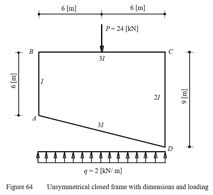
An unsymmetrical closed frame ABCD is considered as shown in Figure 63. The frame is subjected to a point load of P = 24 [kN] at the center of the member BC and a distributed load of q = 2 [kN/m] on the member AD.
| Example 27: Moment in an unsymmetrical closed frame |
| ELPLA DATA-Moments in an unsymmetrical closed frame.rar |
Example 28: Analysis of a plane truss
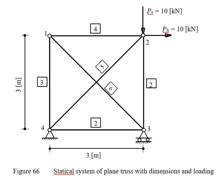
To verify the mathematical model of ELPLA for analyzing plane trusses, results of plane truss introduced by Werkle (2001) (Example 3.1, page 61) are compared with those obtained by ELPLA.
A plane truss of 4 nodes and 6 members is considered as shown in Figure 65. Members 5 and 6 are unconnected in their intersection point. The truss is subjected to vertical and horizontal point loads at node 2, each of 10 [kN].
| Example 28: Analysis of a plane truss |
| ELPLA DATA-Plane truss.rar |
Example 29: Influence of Poisson ratio
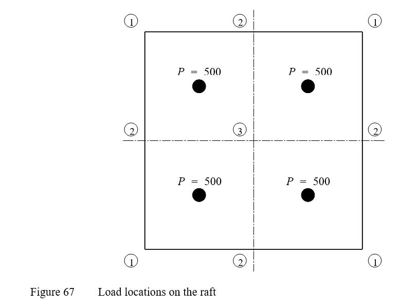
In this example (File qe1 with νs = 0, qe2 with νs = 0.2 and qe3 with νs = 0.5), the influence of Poisson's ratio νs on the settlement S of a rectangular raft 10 × 10 [m2] is studied. Four concentrated loads in the middle of the raft are chosen, each of P = 500 [kN] as shown in Figure 67.
| Example 29: Influence of Poisson ratio |
| ELPLA DATA-Influence of Poisson ratio.rar |
Example 30: Verifying the interaction between two bridge piers
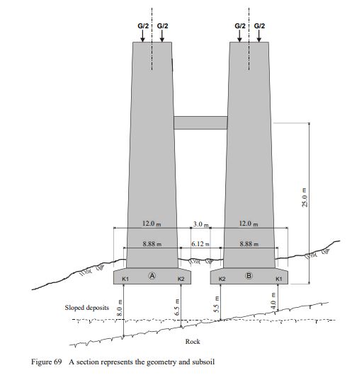
As part of a new highway construction, a two-way bridge consisting of separate, parallel piers for each way direction will be built.
The clear distance between the pier foundations is 3.0 [m]; The foundation is shallow in the sloped deposits in a hanging situation. The governing modulus of compressibility for the deposits was set to Es = 25 [MN / m2]. The rock is considered uncompressible. As an alternative to a low-deformation deep foundation, this example examines the more economical design of a shallow foundation with regard to the foundation cost. In order to reduce the canting of the bridge piers, they are connected at a height of 25.0 [m] above the lower edge of the foundation by a bar. The geometry of the piers and the subsoil are shown in the section in Figure 69 and in Figure 70 in plan view.
| Example 30: Verifying the interaction between two bridge piers |
| ELPLA DATA-Interaction between two bridge piers.rar |
Example 31: Group of isolated footings
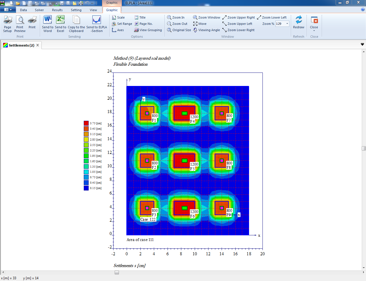
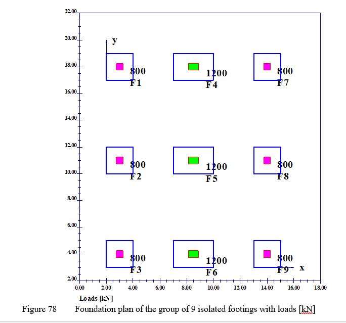
To verify the interaction of a group of footings, the settlement determined using the finite element method under the group of isolated footings from EWB (2003), Example 8.1, page 88, is compared with that obtained by ELPLA. This example is intended to show how the consideration of the stress overlap affects the result of the settlement calculation for a group of footings. Figure 78 shows the foundation plan of the group of 9 isolated footings. They are loaded vertically by supporting a frame structure. The columns transfer the loads of 800 [kN] and 1200 [kN from the superstructure to the footings. Outer columns 1, 2, 3 and 7, 8, 9 have the dimensions 50 x 50 [cm], while inner columns 4, 5, 6 have the dimensions75 x 50 [cm].
| Example 31: Group of isolated footings |
| ELPLA DATA-Group of isolated footings.rar |
Example 32: Displacements of a cantilever beam with a coarse net
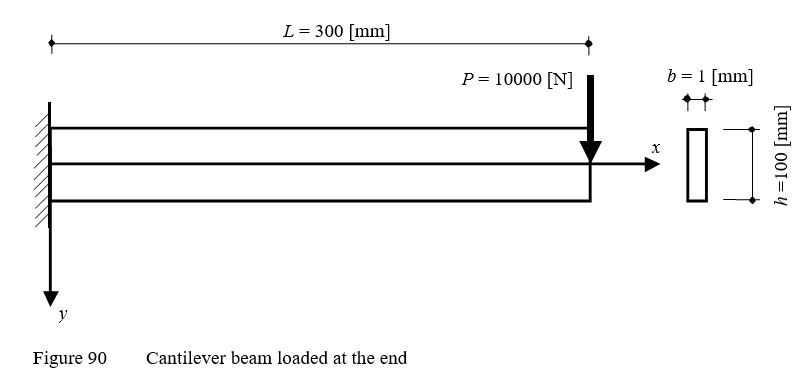
To verify the mathematical model of ELPLA for computing plane stresses, results of a cantilever beam having a thin rectangular cross section introduced by Thakkar (2017) are compared with those obtained by ELPLA. The cantilever carries a point load of P = 10000 [N] applied at the end as shown in Figure 90.
| Example 32: Displacements of a cantilever beam with a coarse net |
| ELPLA DATA-Displacements of a cantilever beam with coarse net.rar |
Example 33: Displacements of a plate with a hole
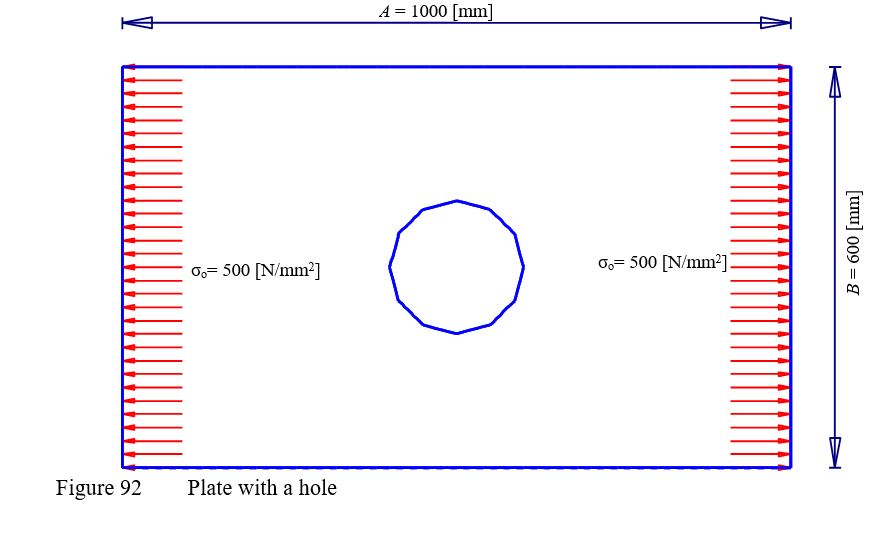
To verify the mathematical model of ELPLA for computing plane stresses, results of a plate with a hole introduced by Thakkar (2017) are compared with those obtained by ELPLA. A rectangular plate of dimensions 1000 [mm] × 600 [mm] and thickness 1 [mm], has a central circular hole of a diameter 200 [mm] as shown in Figure 92. The plate is subjected to a tensile stress σo= 500 [N/mm2] its sides.
| Example 33: Displacements of a plate with a hole |
| ELPLA DATA-Plate with a hole.rar |
Example 34: Stresses beneath a uniformly loaded strip
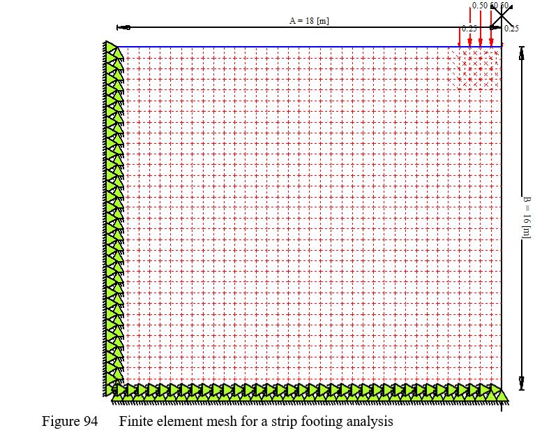
To verify the mathematical model of ELPLA for computing plane stresses, analytical results of a uniformly loaded strip foundation (Figure 94) introduced by Poulos/ Davis (1974), are compared with those obtained by ELPLA.
In the analysis, the applied loading is assumed to be unity (p = 1 [kN/m]) so that the results can be presented as a ratio of the applied load. Width of the load strip is 2b=4 [m].
| Example 34: Stresses beneath a uniformly loaded strip |
| ELPLA DATA-Strip footing stresses.rar |


