Soil models
In ELPLA, different numerical methods with 3 soil models are considered for analyzing raft/piled raft as follows:
- Linear contact pressure
(Simple assumption model) - Constant modulus of subgrade reaction
(Winkler's model) - Variable modulus of subgrade reaction
(Winkler's model) - Modification of modulus of subgrade reaction by iteration
(Winkler's model/ Continuum model) - Modulus of compressibility method for an elastic raft on half-space soil medium
(Solving system of linear equations by elimination)
(Isotropic elastic half-space soil medium Continuum model) - Modulus of compressibility method for an elastic raft
(Solving system of linear equations by iteration)
(Isotropic elastic half-space soil medium and layered soil medium Continuum model) - Modulus of compressibility method for an elastic raft on layered soil medium
(Solving system of linear equations by elimination)
(Layered soil medium Continuum model) - Modulus of compressibility method for a rigid raft
(Isotropic elastic half-space soil medium and layered soil medium - Continuum model) - Modulus of compressibility method for a flexible raft
(Isotropic elastic half-space soil medium and layered soil medium- Continuum model)
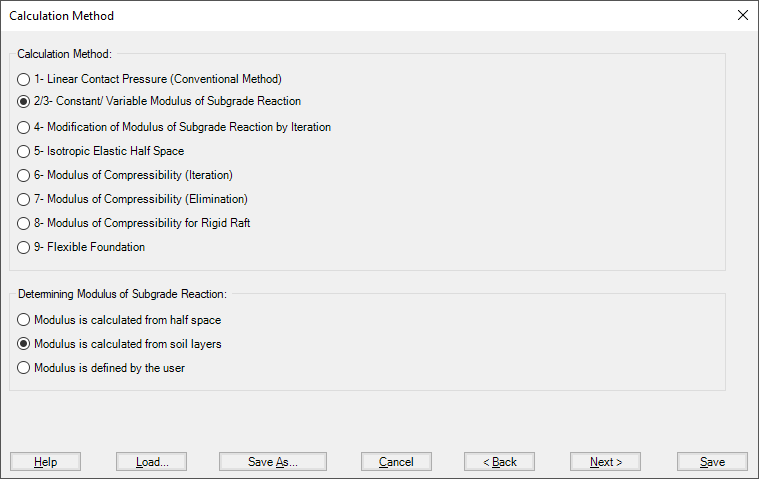
Figure 20 "Calculation methods" Dialog box
- 1- Modulus of subgrade reactions
- 2- Simple Assumption Model
- 3- Winkler’s Model
- 4- Isotropic Elastic Half-Space Model
- 5- Layered Soil Model
In ELPLA, it is possible to analyze the raft by the modulus of the subgrade reaction method in which the modulus can be determined in three ways:
- Modulus is defined by the user
- Modulus is calculated from Half-space
- Modulus is calculated from soil layers
In item a), the user can define a constant modulus for the entire raft (Method 2) or a variable modulus at nodes (Method 3).
In items b) and c) the modulus is calculated through the settlement calculation of the soil depending on boring logs and soil properties.
It is possible to perform linear and nonlinear analyses of the soil models.
There is no interaction between the subsoil and the foundation for the Simple Assumption model (Linear Contact Pressure method - method 1). Therefore, the soil data are not required in this method (only groundwater Gw and foundation level Tf are required). When soil properties are required to be defined for calculation method 1 (Linear Contact Pressure method), the following Dialog box of Figure 21 appears.
If the water table is located above the foundation, the foundation will be exposed to additional negative pressure. In the Dialog box of Figure 21 define the groundwater depth under the ground surface Gw in order to take the effect of groundwater pressure in the analysis.
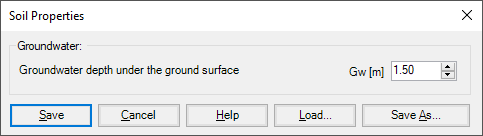
Figure 21 "Soil properties" Dialog box (method 1)
For the two methods of Constant and Variable Modulus of Subgrade Reaction (methods 2 and 3), when the modulus of subgrade reaction is required to be defined by the user, soil properties, in this case, will be the modulus of subgrade reaction ks besides its coordinates (x, y) in the global system and groundwater depth under the ground surface Gw. If the nonlinear analysis is required, the ultimate bearing capacity of the soil qult must be defined (Figure 22).
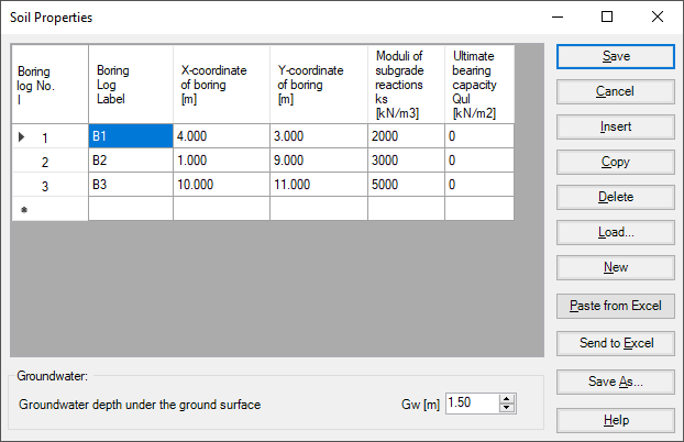
Figure 22 "Soil properties" Dialog box (methods 2 and 3)
When soil properties are required to be defined for calculation method 2 (Modulus of subgrade reaction is determined from Half-Space) and calculation method 5 (Isotropic Elastic Half-Space), the following Dialog box appears.
In the Dialog box, define the settlement reduction factor α, Poisson’s ratio of the soil νs, groundwater depth under the ground surface Gw and the modulus of compressibility of the soil Es. If the nonlinear analysis is required, the angle of internal friction φ and the cohesion c of the soil must be defined.
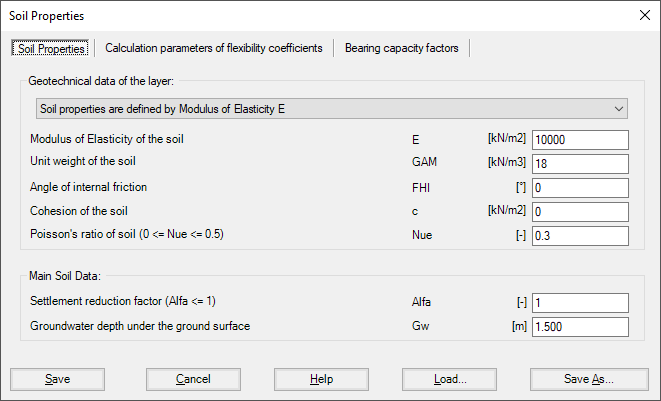
Figure 23 "Soil properties" Dialog box (methods 2 and 5)
Settlement reduction factor
Based on experience, the real consolidation settlements are different from those calculated. Therefore, the settlement s may be multiplied by a factor α according to the German standard DIN 4019. According to the German standard DIN 4019, the following reduction factors α can be applied:
| - Sand and silt | α = 0.66 |
| - Normally and slightly overconsolidated clay | α = 1.0 |
| - Heavily overconsolidated clay | α = 0.5-1.0 |
Flexibility coefficients for interior nodes
For rigid and elastic rafts, it is convenient to determine the flexibility coefficient of the interior node at the characteristic point of the loaded area on that node. For a flexible foundation, it is real to determine the flexibility coefficient of the interior node at that node.
It is possible to determine the flexibility coefficient of the interior node due to a uniform load at that node (Figure 24):
- at the characteristic point of the loaded area, where rigid settlement is equal to the flexible settlement
- at the midpoint of the loaded area, where maximum settlement occurs
- at the interior node on the loaded area
Flexibility coefficients for exterior nodes
The earlier version of ELPLA determines flexibility coefficients for both interior and exterior nodes by assuming uniform loaded areas on these nodes. This assumption requires the principle of superposition for determining the flexibility coefficients. Now it is possible, optionally to convert the loaded areas on exterior nodes to point loads, Figure 24. In this way, the program does not follow the principle of superposition in the analysis, making it much faster than the old analysis. The new method of analysis is consequently faster and more efficient for problems that contain a large finite element mesh.
Limit distance
If the distance between two nodes is too large, the settlement of a node due to a load on the other will be small enough to be neglected. To reduce the time required for determining the flexibility coefficients for great rafts, a limit distance between node i and j for determining the flexibility coefficient c (i, j) may be defined.
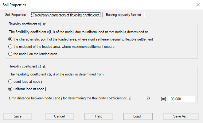
Figure 24 "Calculations parameters of flexibility coefficients" Dialog box (methods 2 and 5)
Bearing capacity factors
The bearing capacity factors used to determine the ultimate bearing capacity can optionally be defined according to different codes and authors. These factors are required to carry out the nonlinear analysis of the soil. The bearing capacity factors are defined according to (Figure 25):
- German Standard DIN 1054
- Euro Code EC 7
- Egyptian code ECP
- Terzaghi
- Meyerhof
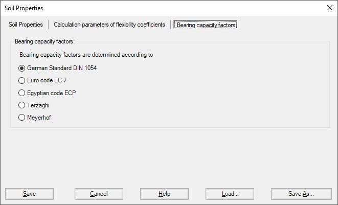
Figure 25 "Bearing Capacity factors" Dialog box (methods 2 and 5)
A layered soil model is used in the analysis of the calculation methods shown in Table 1. When soil properties are required for one of the calculation methods shown in this Table, the following Soil Properties Tab View appears (Figure 26).
Table 1 Numerical calculation methods (Layered soil model)
| Method No. |
Method |
| 2 | Constant modulus of subgrade reaction Winkler's model, Modulus of subgrade reaction is determined from soil layers |
| 3 | Variable modulus of subgrade reaction Winkler's model, Modulus of subgrade reaction is determined from soil layers |
| 4 | Modification of modulus of subgrade reaction by iteration Winkler's model/ Continuum model |
| 6 | Modulus of compressibility method for an elastic raft on layered soil medium Solving system of linear equations by iteration Layered soil medium ‑ Continuum model |
| 7 | Modulus of compressibility method for an elastic raft on layered soil medium Solving system of linear equations by elimination Layered soil medium ‑ Continuum model |
| 8 | Modulus of compressibility method for a rigid raft on layered soil medium Layered soil medium ‑ Continuum model |
| 9 | Modulus of compressibility method for a flexible foundation on layered soil medium Layered soil medium ‑ Continuum model |
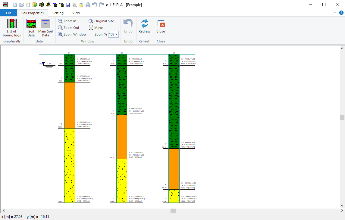
Figure 26 "Soil properties" Tab view


