Geometry and loads
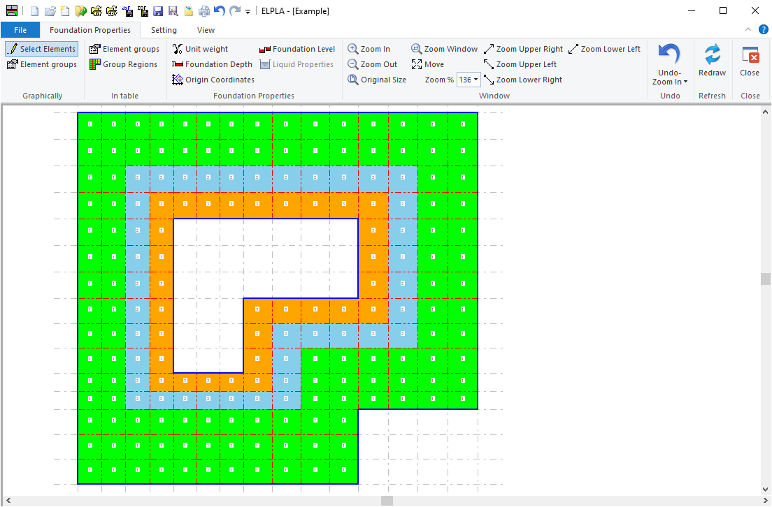
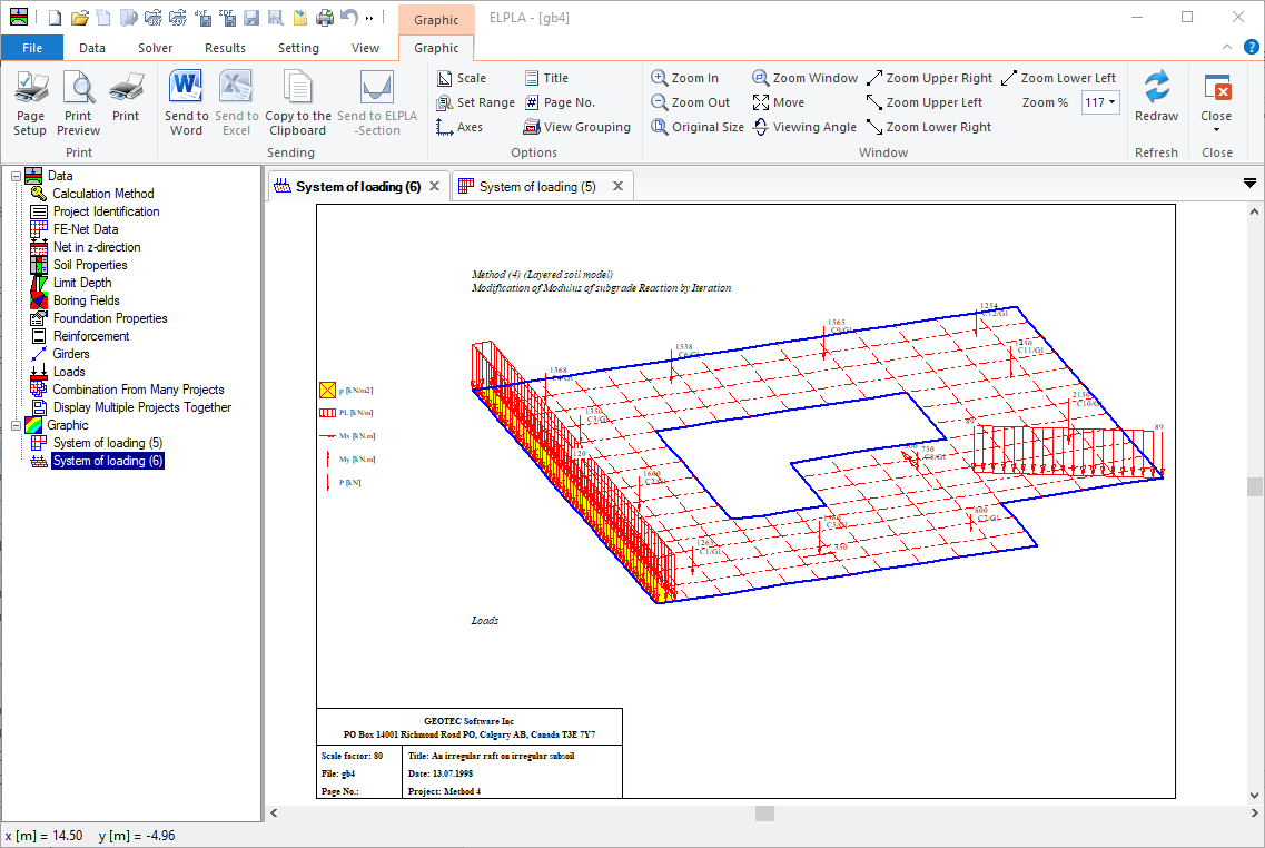
It is possible to consider raft with any arbitrary shape including holes, Figure 36. It is also possible to consider rafts with variable thickness, Figure 37. Loads on the raft can be applied independently on the mesh at any position. Loads may be defined in different types such as point loads, line loads, and polygon uniform loads, Figure 38.
FE-Net
Different element types are developed to generate the FE-Net of the slab according to the Grid-based approach for both triangular and rectangular elements and according to Delaunay’s triangular generation for triangular elements. A new FE-Net is created. When choosing the File - New command and the following templates for different types of FE-Net appear (Figure 39). Using these templates, FE-Net can be generated according to the following features:
-
Generating the FE-Net for square, rectangular and irregular slabs using 6 different types of nets, Figure 40.
-
Generating the FE-Net for circular and ring slabs using 15 different types of nets, Figure 41.
-
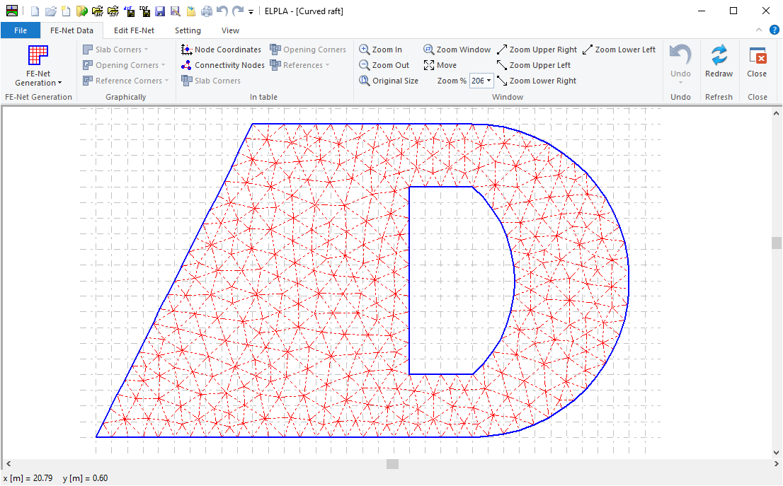
Generating an irregular slab with openings and arc boundaries using a refined mesh, Figure 42.
-
It is possible to use combined rectangular, quadratic and triangular finite elements at the same time for the slab, Figure 43.
-
It is possible to create slab corners, opening corners, and reference corners graphically using CAD-style, which lets the definition of the net quick and easy, Figure 44.
-
In ELPLA, there are two alternative methods to define slab corners, opening, and references either by Mouse or by editing in a table, Figure 45.
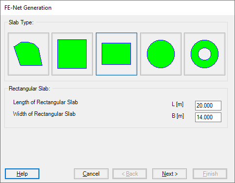
Figure 39 Templates for different types of FE-Net
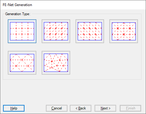
Figure 40 Generation type for square, rectangular and irregular slabs
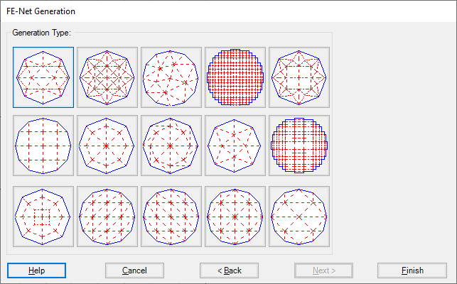
Figure 41 Generation type for circular and ring slabs
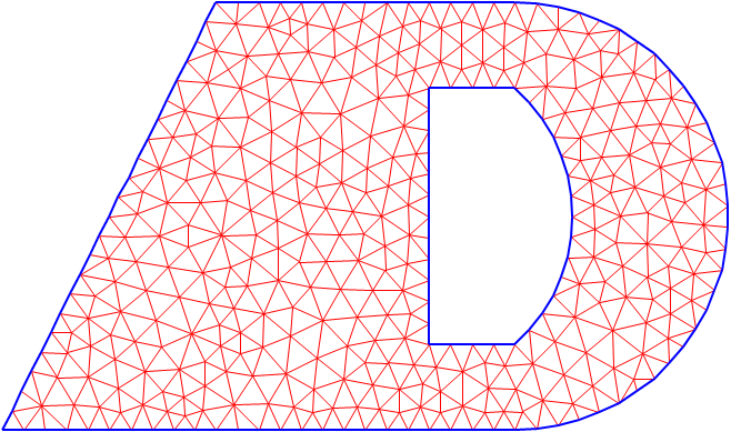
Figure 42 Irregular slab with triangular finite elements
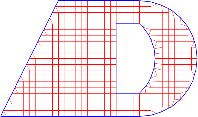
Figure 43 Irregular slab with combined rectangular, quadratic and triangular finite elements
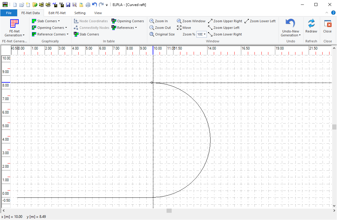
Figure 44 Drawing slab corners graphically by mouse
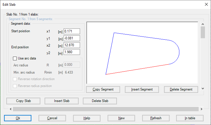
Figure 45 Defining slab corners in a table
-
It is possible to optimize the dimension of FE-Net by making all elements have nearly the same area as possible as by the option "Smoothing the mesh", Figure 46.
-
It is possible to direct and arrange all elements on the slab borders (Figure 47). This option is useful to present contact pressures at raft edges in a good manner when analyzing the raft by Continuum model, in which the contact pressures at raft edges are higher than that at the middle.
-
It is possible to refine the mesh in a specified region such as around supports, springs, and piles to present the concentration of stress, moment, and settlement in this region (Figure 48).
-
By selecting the "Merge Nets" command from the "Arrange" group, two or more nets (Figure 50) can be combined into a net, Figure 49.
-
By selecting the "Split Net" command from the "Arrange" group, the FE-Net (Figure 49) can be divided into two or more nets, Figure 50.
-
Reference points, reference lines, reference corners, Reference polylines, and curves (Figure 51) can be imported into ELPLA from a DXF file (AutoCAD Drawing Exchange File), Figure 52.
-
The user can generate a finite element mesh using the AutoCAD command as "3DFACE", Figure 53. 3D Face can be imported into ELPLA, Figure 54.An existed FE-Net can be added to the current "FE-Net". This option enables the user to analyze a system of many foundations together in one combined FE-Net, Figure 55.
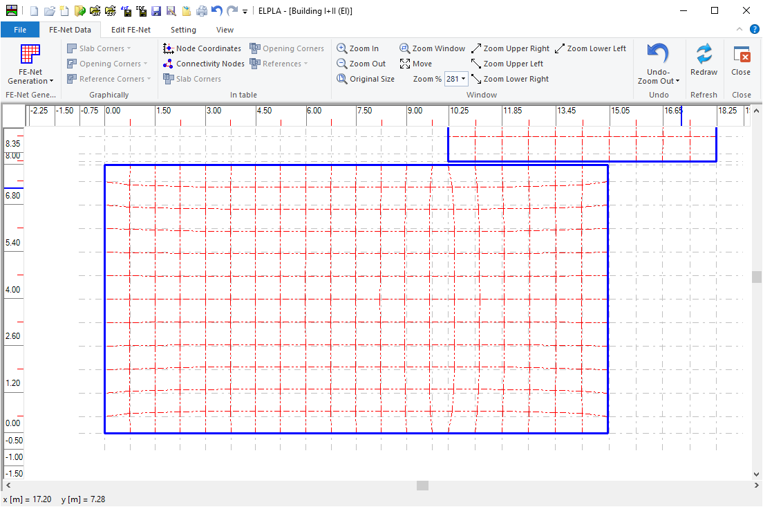
Figure 46 Smoothing the mesh
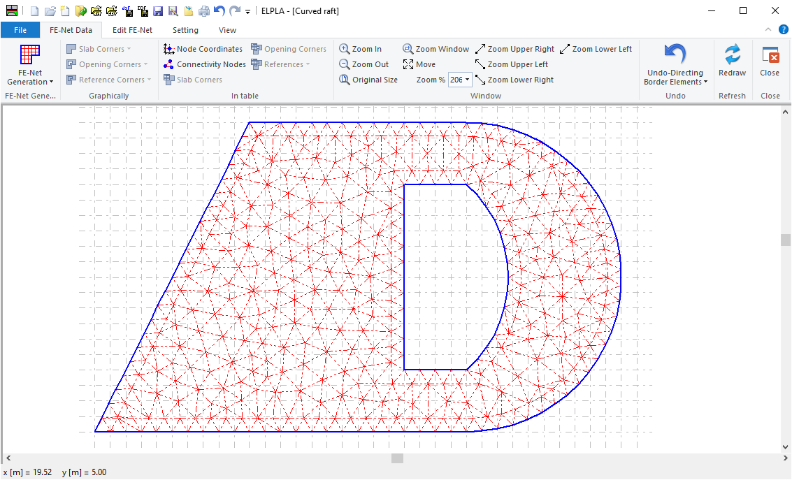
Figure 47 Directing border elements
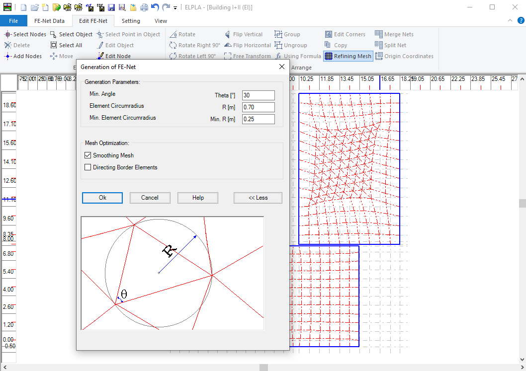
Figure 48 Refining the mesh around specified nodes
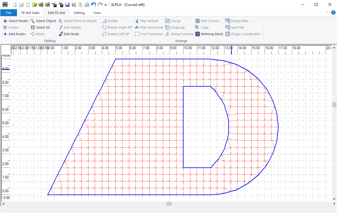
Figure 49 the merged mesh
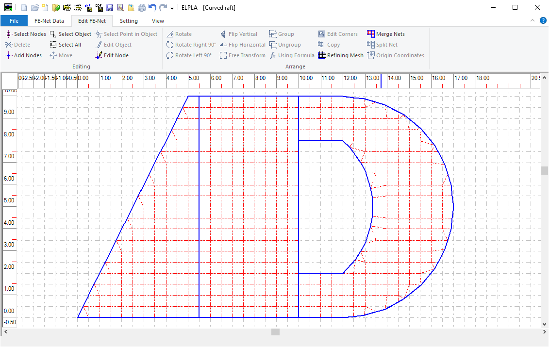
Figure 50 divided net
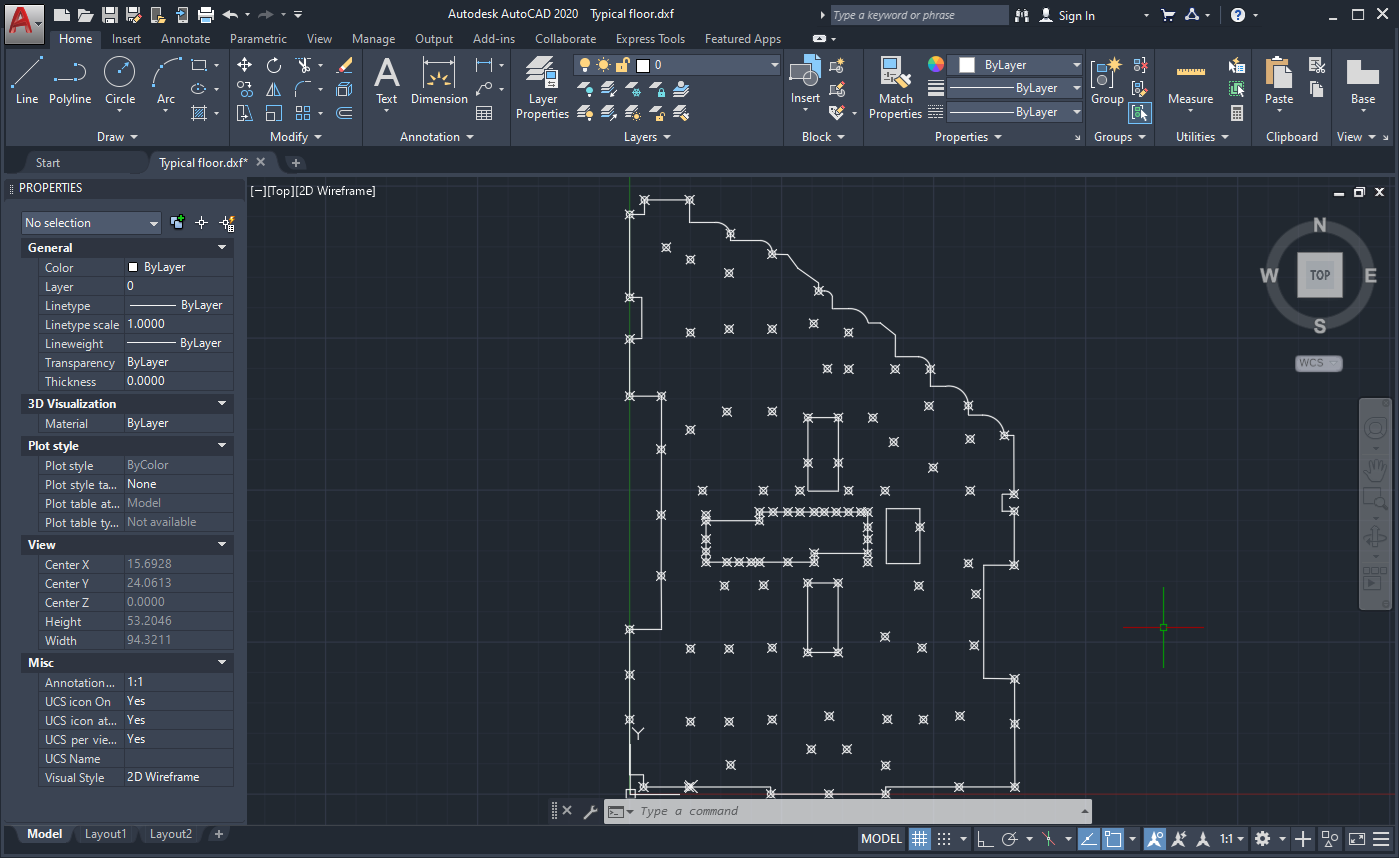
Figure 51 DXF references to be imported into ELPLA
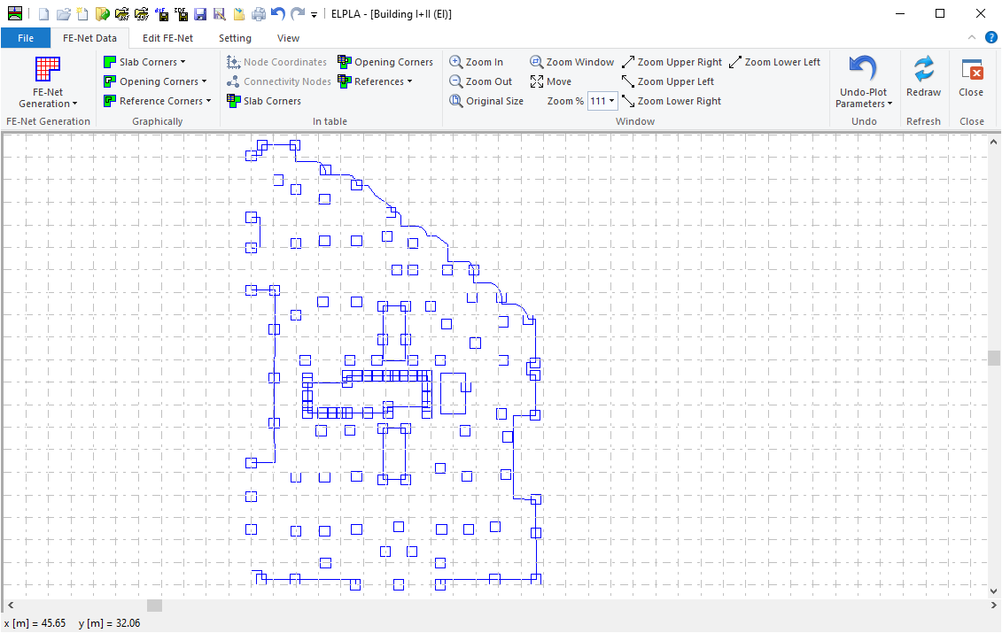
Figure 52 DXF references as ELPLA references
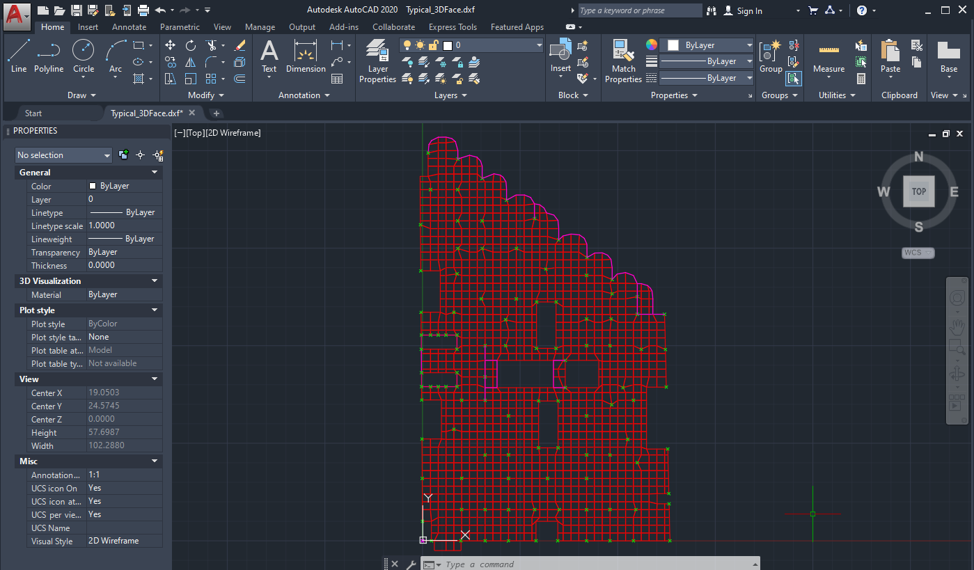
Figure 53 Finite element mesh created by command "3DFACE" in AutoCAD
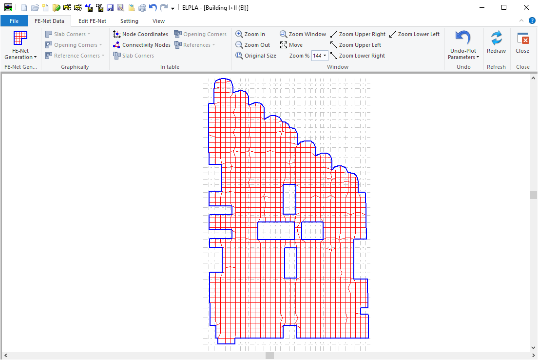
Figure 54 FE-Net as "3DFACE" AutoCAD type is imported into ELPLA from a DXF-file
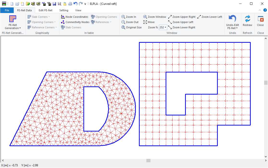
Figure 55 Two FE-Nets together


