تحليل مجموعات الخوازيق
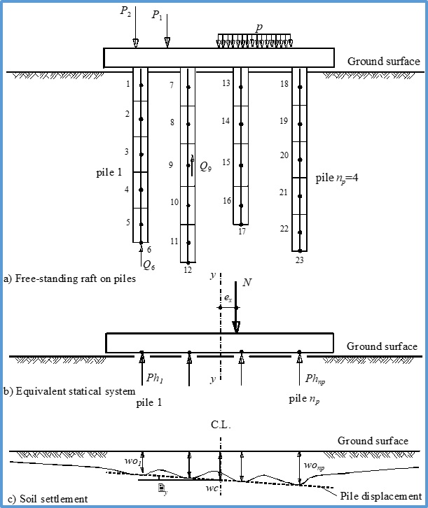
Modeling free-standing raft on pile groups
As a combination of empirical and theoretical approaches, a new method has been developed for the nonlinear computation of pile groups. It meets the requirements of the KPP Directive.
Multiple models for analyzing pile groups
The behavior of the pile-soil system can be examined by considering linearly or nonlinearly analysis.
One distinguishes between the following nonlinear analyses of pile groups by:
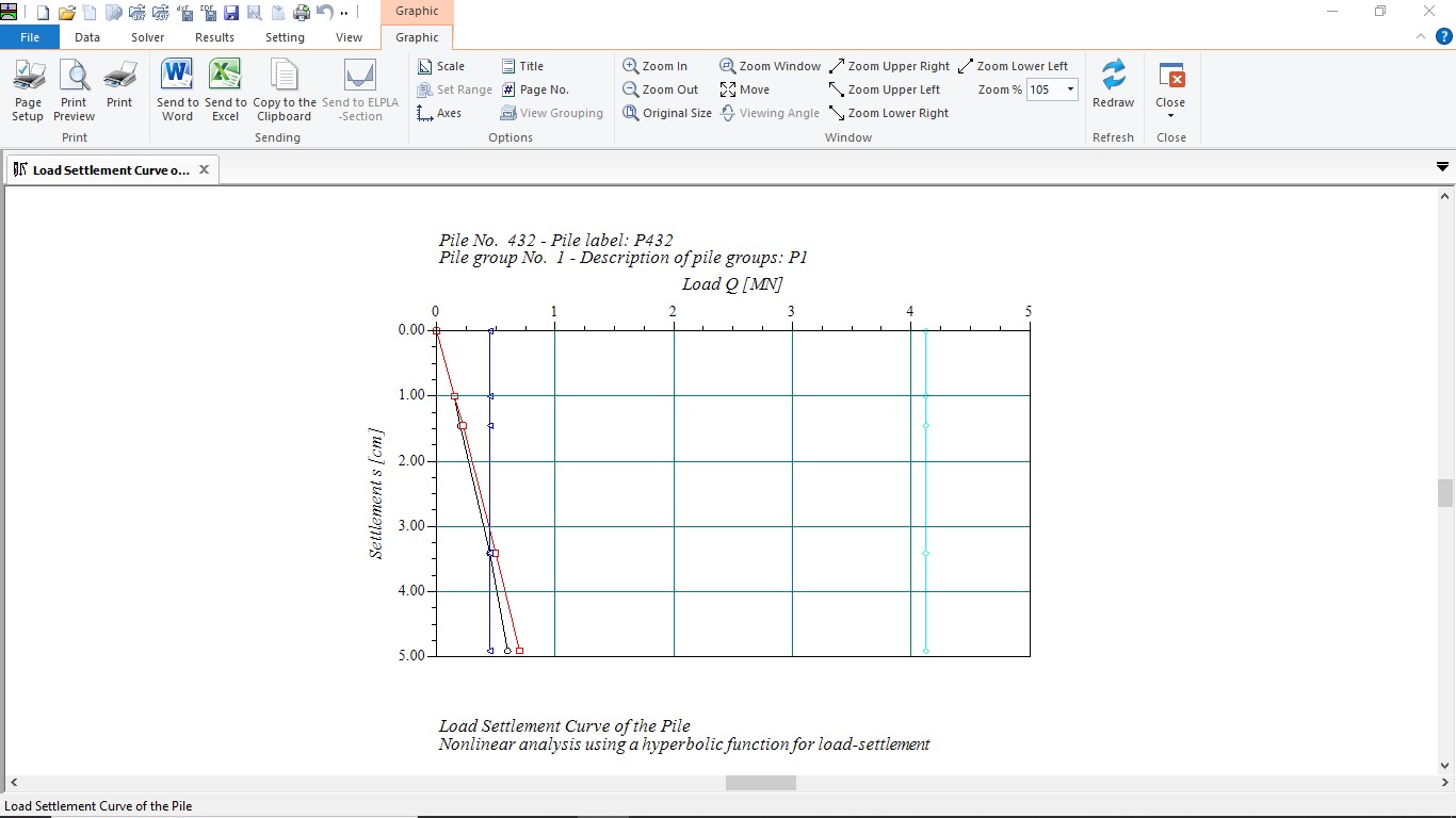
1- A hyperbolic function for the load-settlement curve of the pile
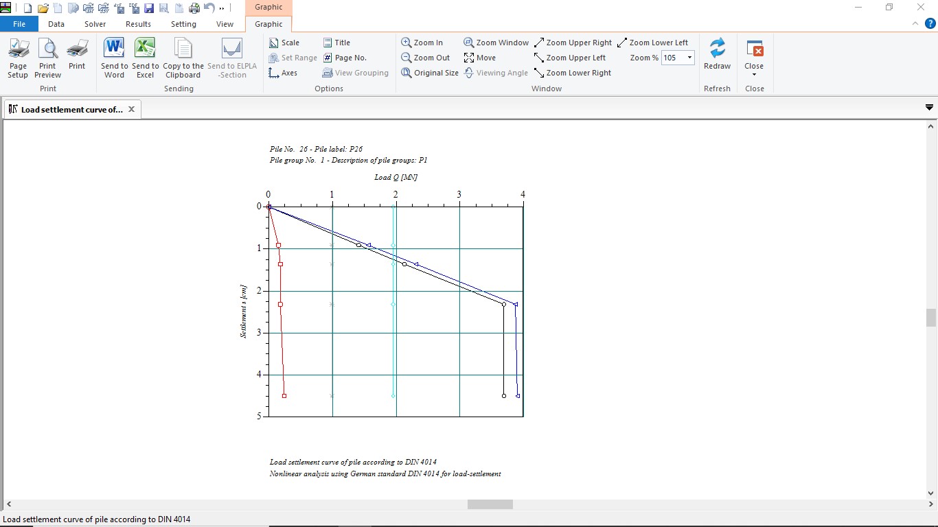
2- Using German Standard "DIN 4014" for the load-settlement curve of the pile
3- Using German recommendations "EA-Piles" for the load-settlement curve of the pile
4- A given load-settlement curve of the pile
المميزات
- User interface and help system are available in 3 languages: English, German and Arabic
- Analysis of an elastic or a rigid combined piled raft foundation
- Analysis of a rigid pile group or free-standing raft on a rigid pile group
- Numerical model of soil-structure interaction is under 9 calculation methods
- Design of the raft according to ACI, EC 2, DIN 1045 and ECP
- Generation of the FE mesh of the raft with different element types
- Automatic generation of the FE mesh of the raft
- Powerful mesh generator (for the generation of square, rectangular, circular and annular rafts)
- Beam elements for modeling stiff walls on the raft
- Translational and rotational springs on the raft can be added at nodes
- Elastic or fixed rotations and deflections can be taken into account
- Determining contact pressures, settlements, internal forces, subgrade reactions, reinforcement and pile loads
- Node coordinates and boundary nodes of the FE mesh can be imported from a table via MS Excel
- Arbitrary shape of slabs, holes are also possible
- Variable slab thickness and foundation depth in vertical and horizontal directions
- Consideration of the reduction coefficients α according to DIN 4019 Part 1
- Point loads, line loads, area loads and moments at any position independent of the finite element net
- Polygonal load with variable ordinates and line moment
- Loading and reloading modulus of compressibility are considered
- The soil is defined by a number of borings each boring has multi-layers with different soil material
- Variable thickness and discontinuous soil strata
- Consideration of the variation of the subsoil in the three directions according to three methods
- Drawing soil layers by different symbols and colors according to DIN 4023 for easy identification
- Consideration of groundwater and overburden pressure effects
- Color representation of the dimensions, slab plans and results on the screen or printer
- Presentation of the results as values in the plan, contour lines, circular diagrams
- Drawing results in isometric view
- Distribution of results in plan
- Drawing deformations as deformed mesh
- Principal moments as streaks
- Drawing sections of results from several calculation methods in one view
- Data and results of several projects can be displayed together
- Tabulation of data and final results on the screen or printer
- Results can be saved in an ASCII file
- The drawings can optionally be saved as a WMF file
- There are detailed explanations in the user manual with numerical examples
- Short help information can be requested at any interface location
- Import or export the data to MS Excel
- Export the results and diagrams to MS Excel
- Export the data and results to MS Word
- A group of data with results together in one presentation
- Copying drawings to the clipboard for use in word processors
Case Study (1): Analysis of Pile Groups of Stonebridge Tower in London by ELPLA
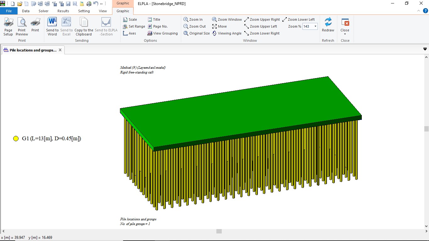
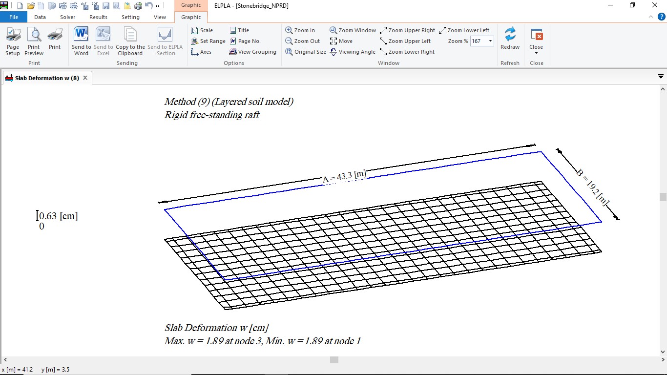
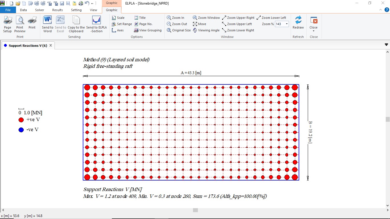
Stonebridge is a tower of 16-storey floors at Stonebridge Park in North London, England.The tower is 43 [m] high. The foundation is a rectangular piled raft of area 43.3 [m] by 19.2 [m]. The estimated total load on the raft gives an average applied uniform load of 187 [kN/m2]. Raft thickness is 0.9 [m]. A total of 351 bored piles are located under the raft. All piles have a length of l = 13 [m] and a diameter of D = 0.45 [m]. Piles are arranged on 1.6 [m] by 1.5 [m] grid.
The tower was constructed between 1973 and 1975, the recorded average settlement of the raft was about 1.8 [cm] after four years from the end of construction. Later measurements indicate that differential raft settlement is small, because the stiffness of the cross-wall superstructure is high.
The foundation of Stonebridge Tower is an ideal case study to verify the analysis of piled raft or pile groups by ELPLA. Using available data and results of Stonebridge Tower piled raft the analysis by ELPLA is evaluated and verified for analyzing a piled raft on clay soil.
| Case Study (1): Analysis of Pile Groups of Stonebridge Tower by ELPLA |
| Stonebridge data |
Case Study (2): Analysis of Pile Groups of Dashwood Tower in London by ELPLA
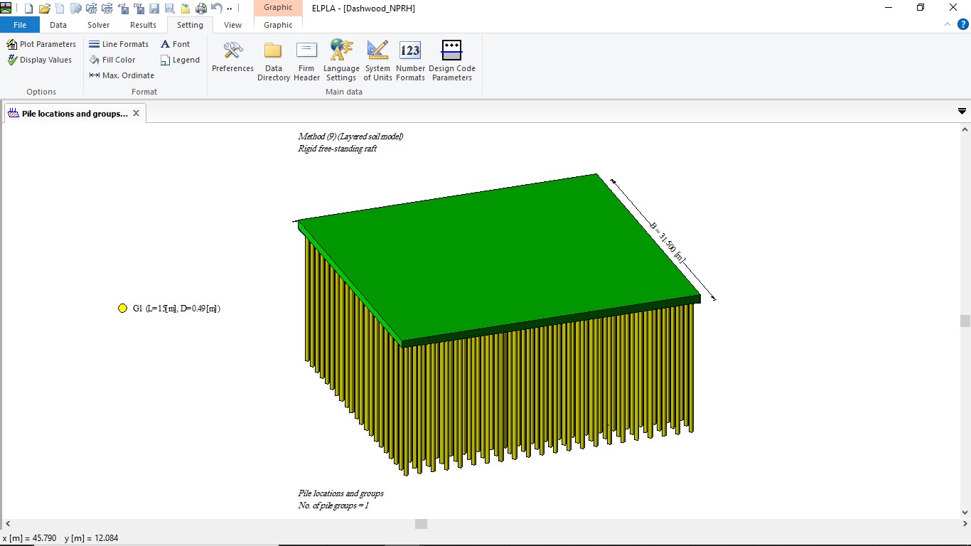
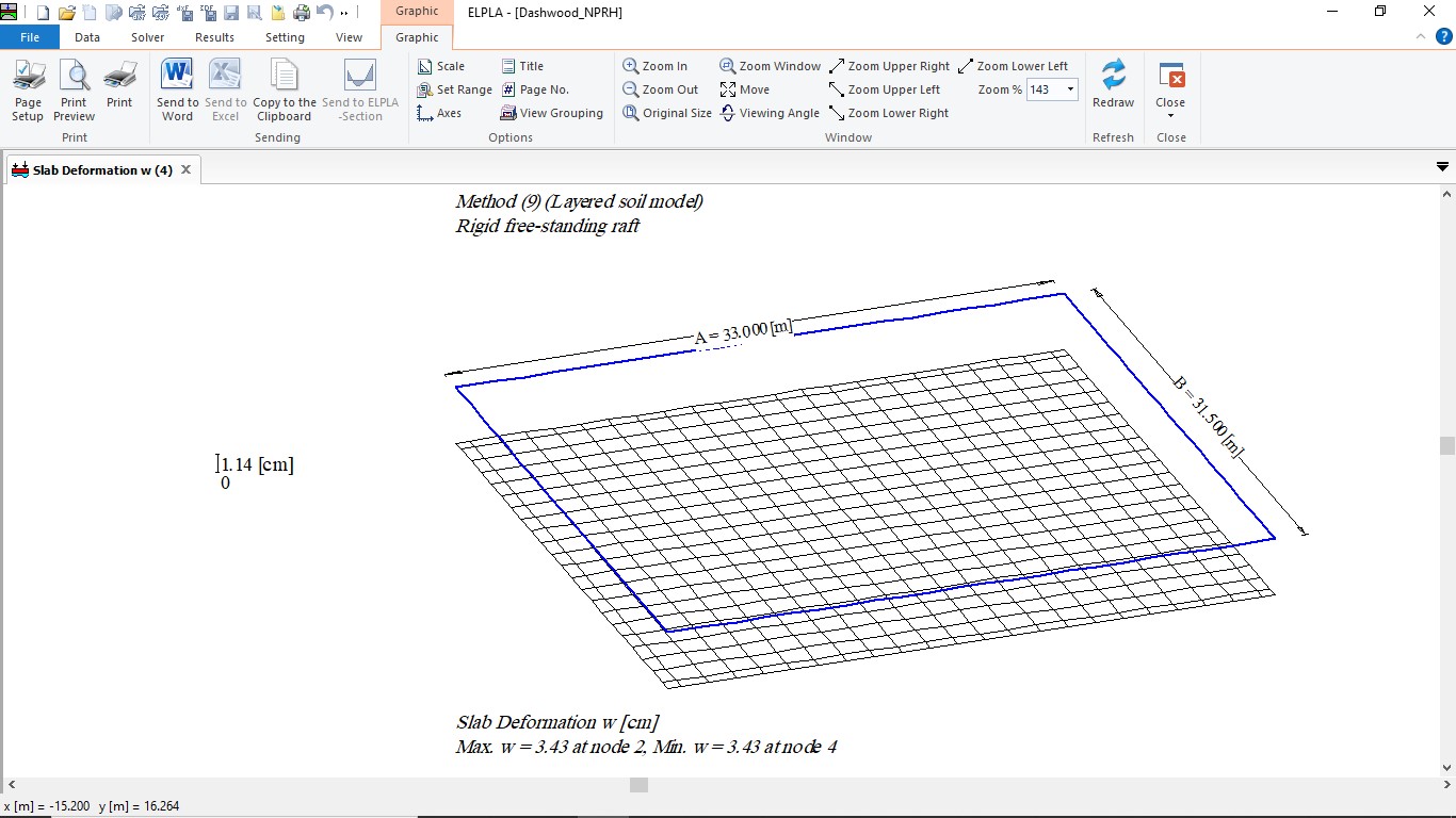
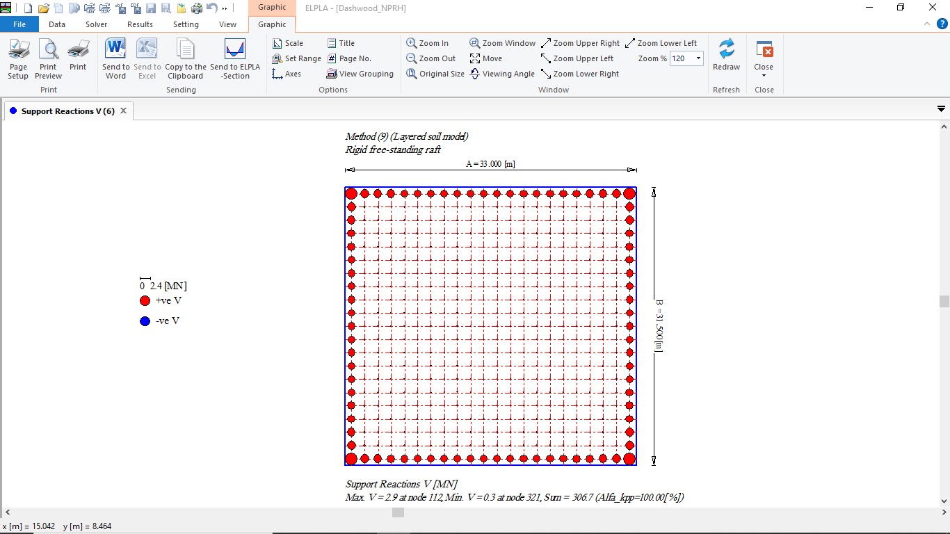
Dashwood House is a high building of 15-storey floors with a single storey basement located in North London, England. The building is 61 [m] high. The foundation of Dashwood House is a rectangular piled raft of area 33 [m] by 31.5 [m]. The building load including the raft weight is 274 [MN].
A total of 462 bored piles are located under the raft. All piles have a length of l = 15 [m] and a diameter of D = 0.485 [m]. Piles are arranged on a square grid of 1.5 [m] interval.
In this case study, the computed and measured settlement of this piled raft is used to verify the methods for analyzing piled raft and pile groups available in ELPLA.


