alt

Description of the problem

This example shows the analysis and design of a group of footings resting on an elastic foundation by two different structural systems. In the first one, the group of footings has no connections while in the second one, the group of footings is connected together by stiff tie beams considering the interaction effect among footings, tie beams and the subsoil as one unit.

Finally, a comparison is carried out between the two structural systems. It is obviously that, if there is no accurate method to determine the stress due to the interaction between the footings and tie beams, the purpose of the presence of the tie beams in this case will be only carrying the walls of the ground floor. Where it is impossible to construct the walls directly on the soil. In the other case, the presence of the tie beams is unnecessary when walls for the ground floor are not required. It is impossible in any way to depend on the tie beams for reducing the deferential settlements for footing or footing rotations without perfect knowledge about the extent of their effect in the structural analysis accurately.

The program ELPLA has the possibility to composite two types of finite elements in the same net. In which, the footings are represented by plate elements while the tie beams are represented by beam elements. Thus, footings and tie beams can be analyzed correctly.

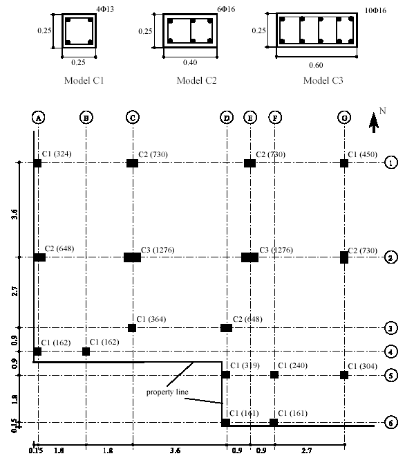
Figure (87) shows a layout of columns for a multi-storey building. The columns are designed to carry five floors. The dimensions of columns, reinforcement and column loads are shown in the same Figure (87).

It is required to design the building footings considering property lines at the west and south sides of the building (a neighbor building). The design must be carried out twice. In the first one, the footings are designed as isolated footings without connection among them, while in the second, the footings are designed as connected footings with tie beams to reduce the differential settlements among them and footing rotations.

alt

Description of the problem

Ring or circular rafts can be used for cylindrical structures such as chimneys, silos, storage tanks, TV-towers and other structures. In this case, ring or circular raft is the best suitable foundation to the natural geometry of such structures. The design of circular rafts is quite similar to that of other rafts.

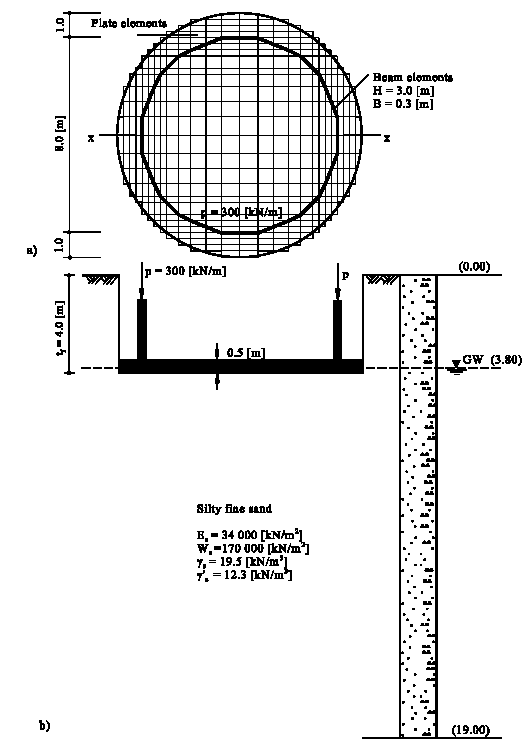
As a design example for circular rafts, consider the cylindrical core wall shown in Figure (35) as a part of five storeys-office building. The diameter of the core wall is 8.0 [m], while the width of the wall is B = 0.3 [m]. The core lies in the center of the building and it does not subject to any significant lateral applied loading. Therefore, the core wall carries only a vertical load of p = 300 [kN/m]. The base of the cylindrical core wall is chosen to be a circular raft of 10.0 [m] diameter with 1.0 [m] ring cantilever. A thin plain concrete of thickness 0.15 [m] is chosen under the raft and is not considered in any calculation.

Two analyses concerning the effect of wall rigidity on the raft are carried out in the actual design. Both by using the Continuum model (method 6) to represent the subsoil. The two cases of analyses are considered as follows:

Case 1:The presence of the core wall is ignored.

Case 2: A height of only one storey is taken into account, where the perimeter wall is modeled by beams having the flexural properties of B = 0.3 [m] width and H =3.0 [m] height. The choice of this reduced wall height because the wall above the first floor has many openings.

Figure (35) shows plan of the raft, wall load, dimensions and mesh with section through the raft and subsoil. The following text gives a description of the design properties and parameters.

alt

Description of the problem

An example is carried out to design a spread footing according to EC 2, DIN 1045, ACI and ECP codes.

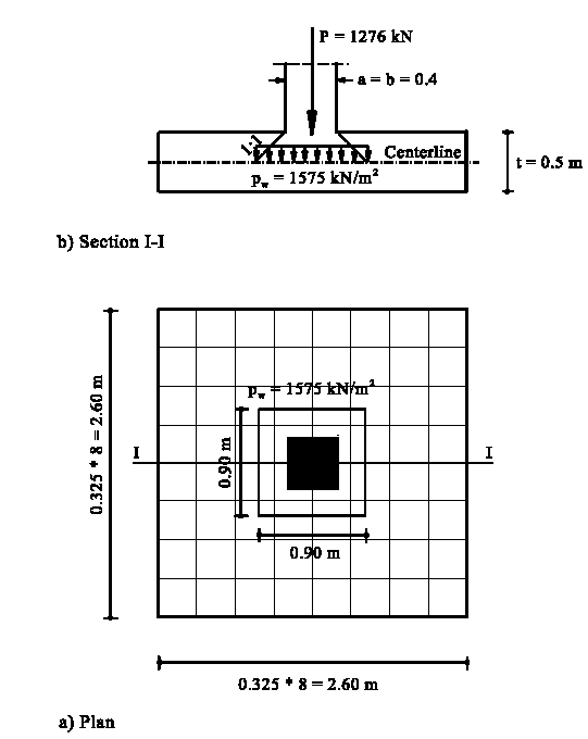
A square footing of 0.5 [m] thickness has dimensions of 2.6 [m] × 2.6 [m] is chosen. The footing is support to a column of 0.4 [m] × 0.4 [m], reinforced by 8Φ16 and carries a load of 1276 [kN]. The footing rests on Winkler springs have modulus of subgrade reaction of ks = 40000 [kN/m3]. A thin plain concrete of thickness 0.15 [m] is chosen under the footing and is not considered in any calculation.


alt

Description of the problem

A ribbed raft may be used where the distance between columns is so great that a flat raft requires excessive depth, with resulting high bending moments. Consequently, the volume of concrete is reduced. A ribbed raft consists of a stiffened slab by girders in x- and y-directions. The girders on the raft may be either down or up the slab. Ribbed rafts can be used for many structures when a flat level for the first floor is not required. Such structures are silos, elevated tanks and various other possible structures. Although this type of foundation has many disadvantages if used in normally buildings, still uses by many designers. Such disadvantages are: the raft needs deep foundation level under the ground surface, fill material on the raft to make a flat level. In addition, a slab on the fill material is required to be constructed for the first floor. The use of the ribbed raft relates to its simplicity in analysis by traditional manners or hand calculations. Particularly, if the columns are arranged in lines. The ribbed raft generally leads to less concrete quantity than the flat raft, especially if the columns have heavy loads and large spans.

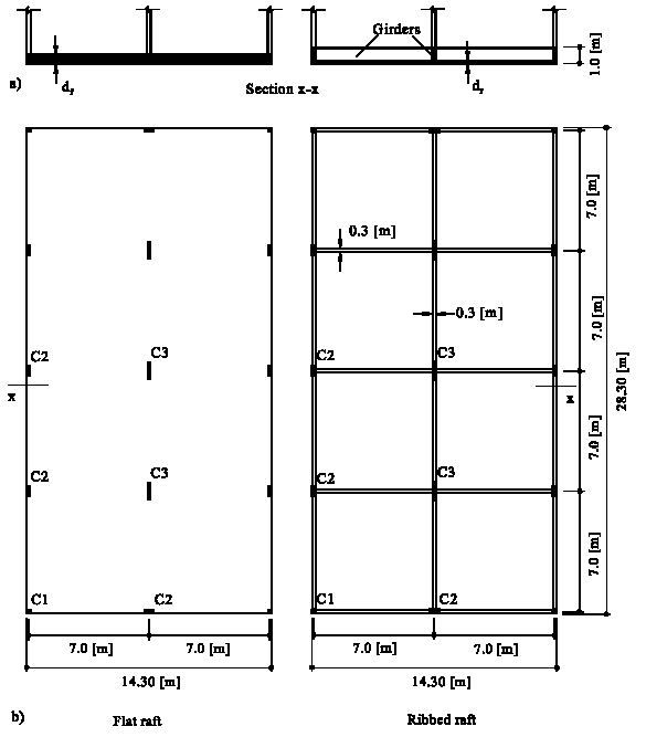
In this example two types of rafts, flat and ribbed rafts, are considered as shown in Figure (49). The length of each raft is L = 14.3 [m] while the width is B = 28.3 [m]. Each raft carries 15 column loads and a brick wall load of p = 30 [kN/m] at its edges. Width of ribs is chosen to be bw = 0.30 [m] equal to the minimum side of columns, while the height of ribs including the slab thickness is chosen to be hw hf = 1.0 [m]. Column dimensions, reinforcement and loads are shown in Table (53). A thin plain concrete of thickness 0.20 [m] is chosen under the raft and is not considered in any calculation.


alt

Description of the problem

Many soil models are used to analysis of raft foundations. Each model gives internal forces for the raft different from that of the others. However, all models are considered save and correct.

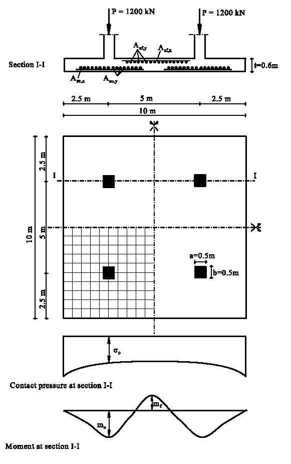
This example is carried out to show the differences in the design results when the raft is analyzed by different soil models. A square raft has dimensions of 10 [m] × 10 [m] is chosen. The raft carries four symmetrical loads, each 1200 [kN] as shown in Figure (22). Column sides are 0.50 [m] × 0.50 [m], while column reinforcement is 8Φ19. To carry out the comparison of the different codes and soil models, the raft thickness is chosen d =0.6 [m] for all soil models and design codes. The raft rests on a homogeneous soil layer of thickness 10 [m] equal to the raft length, overlying a rigid base. The modulus of compressibility of the soil layer is Es = 10000 [kN/m], while Poisson's ratio of the soil is νs = 0.3 [-].

The three subsoil models: simple assumption model, Winkler's model and Continuum model (Isotopic elastic half-space soil medium and Layered soil medium) are represented by four mathematical calculation methods that are available in program ELPLA.

About GEOTEC Software

GEOTEC Software is providing universities and consulting companies with the right tools for the last 25+ years. We also assist our clients in various geostructural projects. From basic to advanced problems, GEOTEC Software can provide you with the right technical assistant.

Language

Select your language

Search

Search